Here's a collection of vero (stripboard) and tagboard guitar and bass effect layouts that we have put together covering many classic and popular effects in growing numbers. Many of these have been posted on freestompboxes.org, so check that site out for great discussions on building your own effect pedals. Enjoy the builds and please also visit us on Facebook and Twitter
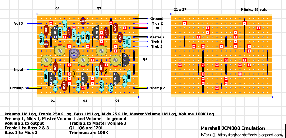
And another, being a classic rock guy this one appeals to me a lot! I can't find a lot of info about the source of the schematic, but looking at the JCM800 2204 scheme it is extremely close. As usual, use the trimmers to set the JFET drains (other than Q4) to between 4.5 and 5V.
I'm not sure if the pedal in this video uses the same schematic verbatim, but it should be very close if based on the JCM800 amp scheme and so should give a good idea of what to expect.
Happy Fathers day to all you dads! I had a few hours this afternoon, and built this pre-amp. it works although it isnt very loud. I had to dime the master and the volume. I bridged the cut between the 100n off the volume 3 connection to the 100 meg resistor, now it sounds right, from the schematic the cut should'nt be there? Sorry i ran out of time and have to go for dinner. i cant test the tone stack, athough the seem to be right. But I just wanted to give my 2 cents
Yes happy fathers day everyone, I got a big mug with DAD on it and a pair of slippers saying "KEEP CALM AND GET ME A BEER" which is nice :o)
Thanks for the feedback on the layout. The 100n cap is the output cap from Q6 drain and is correct to the schematic. Look at the far right hand side, drain > 100n > volume pot lug 3. If the volume is low then something is wrong, measure all the JFET pin voltages just to see if something stands out
No they don't need to be matched, and socket them and try any other JFETs you may have hanging around. I've seen these emulators built with 2N5457's and 2SK30's in the past so it's always worth auditioning other types.
these were some of the mods that were suggested for this build by stratman7000 on diysb
1) Remove the 470pf Cap from input stage. It will make the tone controls more useful, and the pedal less bright 2) Remove the 470pf cap from the preamp stage. It will further make the controls more useful, and the pedal less brittle 3) To increase the Gain Remove the 10k resistor on the PREAMP and change it to 4.7k NOTE anything lower is overkill. 4) My personal favorite: use a 2N5457 Transistor for Q4 it will add squishyness and dynamics and a hotter output.
"KEEP CALM AND GET ME A BEER" - LOL :) Yeah i saw in the schematic and what you are saying Mark. This was the first build where is set the trimmers, first to around 4.5v (except Q4) before i plugged my guitar into it. I removed my bridge and reused the cut between 100n and 100K resistor. I forgot the 22n near Q6. I installed that cap now i have good volume. Unfortunately i had to keep my amp low (sleeping kids). But the tone controls work. Good crunch on this one I will play it when i get home from work, and verify it then......is there a way to put in a "super lead" setting in this like the DLS mk3? I built that one and like it a lot.
One of the things the Superlead setting on the DLS MkIII does is swapping the 680n cap at the source of Q1 to 22u. I'd try that first, just taking a wire from Q1 source to lug 2 of a DPDT on/on switch, solder a 22u cap between lugs 1 and 4 (negative to 4) and then connect lug 5 to ground. So in one position the 680n will be in circuit, in the other position the 22u will be put in parallel with it giving you around 22.68uF. See how that works.
The mods done to the amp slash presumably used to record appetite for destruction with. Its the one he tried to steal from s.i.r. studios:) George lynch was also fighting for it back then. There was one extra gain stage added. There are schematics on the web. Maybe i'll try to find em and link em but you'll probably do a better job.
Oddly I have never played a JCM800 (well except the 2012 1w serie), and was wondering why there is a volume + MV on a single channel amp ? How do they interact ?
The preamp is really just a volume control too so there are 3 in it altogether. If you have the preamp and master volume dimed and then control the output level with the final volume control it means the maximum signal is hitting the stages and so you should get more distortion from it. Or you can control the volume earlier on so the signal hitting the stages is reduced and so is the dirt. I suppose it's mimicking a normal amps preamp and power amp distortion.
Probably I was wondering because after checking a few 2204 layouts on the web, it seems there is no volume pot but a presence one instead. Anyway, pedal on the demo sounds great so definitely on the to do list :D Thanks
Hi Mark: Thanks for the handy info. You can tag this one. I was going to add the "super Lead" switch, but this one doesn't need it. Sensei Tim was right, this one is really bright. i'll looking into getting more bass out of it from Tim's comments.....thanks agian Mark/Mirosol for all your help. Now a Hiwatt dr103 would be a cool emulator, i know that one has good BASS
Hi, long-time lurker but this is my first post. I love this site! Thank you lvlark, Mirasol, and everyone else who's contributed! I'm interested in building this pedal but have some questions regarding Sensei Tim's mod suggestions:
"Remove the 470pf Cap from input stage" & "Remove the 470pf Cap from preamp stage" - I assume those are the bottom two?
and
"...Remove the 10k resistor on the PREAMP and change it to 4.7k " - left one or right one?
I'm getting back into building after some time off and I'm a bit rusty, so if anyone's attempted this, I'd appreciate any info. Thanks in advance!
This comes truly alive with 18V. It being about twice as loud. Here's a little clip of mine, ran with 18V: http://mirosol.kapsi.fi/varasto/circuit_demos/800Preamp.mp3 (Rhythm is master and volume maxed, pre at 9-10 o'clock, played with a strat single coil at bridge position. Lead is master and pre maxed, volume at 9-10 o'clock, played with a strat hot alnico humbucker at neck position)
What comes too biasing, if the sweet spot is around 5V with 9V supply, then the sweet spot for 18V supply should be around 10V. But that doesn't matter as you can bias it with any voltage. The bias/supply ratio doesn't change, no matter what the supply voltage is. And i do recommend using 50k trimmers and tuning the voltages by ear. +m
Cool...thinking of running this circuit into a simple little dual-LM386 power amp so I can have myself a little 1-watt JCM800 in pedal format. Might use two output jacks so it can be used as a pedal or a standalone amp.
Also...I noticed that this layout seems to emulate the High input of the JCM800...is there a way to add a Low input connection to it? As far as I know, the Low input on the original bypasses the first gain stage...
Okay...just opened up my '84 JCM800 2204 and checked the jack wiring...When plugged into the Low input, the guitar signal goes straight to lug 3 of the Preamp volume via the parallel 470K/470pf peaking circuit. The high input takes the 68K to V1 Grid Triode 1 (pin 7). Grid Triode 2 (pin 2) is connected to Preamp Volume 2, so that's Q2 in this layout...
Okay guys, I went through a few options and came up with a minor modification for this layout that allows it to emulate the High and Low inputs on the JCM800 2203 and 2204.
In total, 1 cut was added, 1 capacitor moved (one leg of it), 1 trimmer and it's corresponding cut moved (one space to the right). 2 wires added to the board, and a 3PDT footswitch or On-On mini-toggle for switching between the inputs.
Effectively it bypasses the first gain stage (Q1).
Not tested or verified, but it accomplishes everything that the two cliff jacks in the original amp do. Will be building this soon, so I'll test it myself then.
I present to you, the HighLow mod: http://i.gyazo.com/a98db28a849d2ceff18fcc4ba603d8f4.png
There's a slight volume drop, it's a bit darker and you can coax a lot more Clean Marshall sounds out of it. Takes boosts/od's in front of it really nicely too. I've compared it going into a dual EL34 power amp with my real JCM800, and the Low mode of the pedal sounds identical to the Low input of the Marshall. The High mode is a little more compressed than the High input on the amp, but that could be my biasing.
I also swapped out the first 470k/470pf treble peaker for a 68k resistor (tames the harsh high end, it's something I did to my actual '83 JCM800), and removed the 470pf from the second 470k/470pf peaker. Also added a 0.0015uf cap on the Volume pot, from lug 3 to 1 (cutting some more unwanted highs). Might fiddle with the 100n output cap to tune the bass response. Drop it to decrease, raise it to increase.
super late reply, but i just finished a build with your suggested changes (1n5 cap on volume, 68k in place of the first 470pf/470k pair) and it sounded GREAT! This is how the stock layout should be. IMHO the stock layout sounds way too shrill.
Built it today and got fets biased at 4.7 volt. I used j112 in every socket but the outpu is extremely low and only with all pots max and amplifier volume max i barelly hear it. I double checked everything but seems ok. Are fets the problem?
Okay.... I gave this my best shot but had NO luck, and yes I am sure I trouble-shot it the best I could - with fresh eyes. I guess
Question - someone mentioned taking out the 470p filter caps - do you replace them with jumpers? I did notice that my audio trace tended to end at the second one of these, however I exchanged it and the tranny and still no luck.
I can bias all J201s for 4.5v - so I know I an getting supply throughout, but I do not get audio. Oddly, if I disconnect it from the power supply I get audio all the way through the ciircuit.
I am stumped. I have managed to get through all of the other circuits I have tried - including many with J201s with trimpots - but not this one.
If anyone has successfully built this - and may have noticed some trouble spots, I would really appreciate some guidance as things to watch out for... Thank you.
The first two 470p's (from the left) can just be removed; the 470k resistors in parallel with them carry the signal. I left the third 470p in. That one needs to be jumpered if you removed it.
Besides that...grab a razor blade, give it a run between all the tracks...I've found even flux can bridge and conduct Just enough to cause a short.
Next I would check all of my cuts, links and component placement. It only takes 1 row off to cause havoc.
And finally, if all else fails, rip out all the offboard wires and redo them, making sure all the joints are strong.
Thanks Ryan. I did check all off-board wires too. I wasn't sure. so I tried to jumper those 470pF. I did notice a lot of audio was lost going through those 470pF so jumpering made sense, but I will try just taking them out.
Okay - this is weird. Took out the 470pFs. I also found a cold solder joint & fixed it. Now, everything works but it is very low volume. I decided to try a 2n5457 in Q4, and when I took out the J201 the whole circuit got WAY louder. Now it is better with nothing in that spot.
It sounds loud, I get Bass, mid & treble, & pre. vol & Master Vol. What I don't get is massive overdrive as I expected. Played with the biasing and cannot get any more out of it.
I saw people say they took out the first stage, I can see why. But I now wondering if this is it, or if I still have a problem.
Refusing to put this circuit away, I found a 470R where I was supposed to have 4.7k. Replacing that helped a lot. At that point it was more in the ballpark but I kept wondering why any circuit would sound better with a transistor pulled than present (Q4).
I just wanted to say I got a LOT more gain out of this by replacing the 10k on Q4 source with a 68k. Yes, adding to the resistance here made it surprisingly louder and gainier (less signal going to ground? - I am not sure). This is on the J201 feeding the tonestack. I did not try other values but I imagine there are a lot of variables here. I might suggest a socket here and see what is possible.
I took a look at the 2203 schematic - and the value there (coming off the 12ax7 to ground ahead of the tone stack) is 100k.
Now it sounds better than not having anything, or than having a 2n5457 in Q4.
I just wanted to circle back around to this pedal and design. This design I built up and had a LOT of positive things about it. It was a little too bright and fizzy. Looking over an actual 2203/2204 and in the Phase Inverter circuit. I didn't care for the gain, volume, then master volume. The original circuit only has gain and volume and I don't want to fight volumes thru the circuit.
I would like to build this up again and see how it is. Then, change the values to more represent the 2203/2204 circuit and see if better or not. If it is better...keep it. I'd like to also include a 9V/18V LO/HI switch on it.
I'd like to then add some switches to change a few things such as Jose Arredondo MODs, maybe a 3-position on the NFB as well as 3-way on the presence cap value and possibly add a Depth/Resonance MOD, but first to get the baseline. There has been some suggested MODs over the years.
I also recently purchased a Friedman BE-OD. Again, there are characters very similar to the original amp, but again a little too bright and fizzy and missing a MIDdle control. I will be reverse-engineering it this weekend and work on it's shortcomings. If anyone is interested in the PCB, Layout, and BOM, let me know and we can Vero it also...and work on improvements to the design.
Get a 25k pot. Add a .0022 cap to lug 3 then to ground. Take a wire from master lug 3 to 1&2 on 25k pot. Then add a 1.5 resistor on lug 2 on treble to lug 1&2 on 25k pot.
So, is it possible to drop the last "volume pot", seeing there's already a master volume, and that last one is just your normal "dump signal to ground" style volume control?
What about adding a layout for the PAL 800 JCM Emu? It seems to be very similar, but it has an added trim pot for master tone: http://www.freestompboxes.org/viewtopic.php?f=1&t=28165#p264332
I put used the high/low mod as above, and used a 2n5485 for Q4, but when I cut the 47p the eq became functional but the overall sound was not quite right and the jfets needed rebiasing. That was fine, but it also made the low input completely clean. It sounds better with the 47p in place, so I'll take that rather than a working eq I think.
If I remember my marshall amp mods.... replacing the 2n2, with a 22n cap was a common mod, almost essential, to tame those nasty highs. Would replacing this 2n2 w/ a 22n do the same thing? I'm not too good with schematics.....so I have to ask! LOL
Detroit rock city ! This song reminds me so much great moments :D
ReplyDeleteIndeed your are keeping us very busy Mark, thank you so much for these great layouts
The schematic looks identical to the old ROG Thunderchief v1.X, except the speaker emulator/filter has been removed.
ReplyDeleteHappy Fathers day to all you dads!
ReplyDeleteI had a few hours this afternoon, and built this pre-amp. it works although it isnt very loud.
I had to dime the master and the volume. I bridged the cut between the 100n off the volume 3 connection to the 100 meg resistor, now it sounds right, from the schematic the cut should'nt be there? Sorry i ran out of time and have to go for dinner. i cant test the tone stack, athough the seem to be right. But I just wanted to give my 2 cents
Yes happy fathers day everyone, I got a big mug with DAD on it and a pair of slippers saying "KEEP CALM AND GET ME A BEER" which is nice :o)
DeleteThanks for the feedback on the layout. The 100n cap is the output cap from Q6 drain and is correct to the schematic. Look at the far right hand side, drain > 100n > volume pot lug 3. If the volume is low then something is wrong, measure all the JFET pin voltages just to see if something stands out
Do you still need to match the JFETs since they are all being biased separately???
ReplyDeleteAnd is there anything else I can use other than a J201???
No they don't need to be matched, and socket them and try any other JFETs you may have hanging around. I've seen these emulators built with 2N5457's and 2SK30's in the past so it's always worth auditioning other types.
DeleteHey, that's my video ;)
ReplyDeleteAnd yes, that build was almost identical to this vero layout.
Thanks for the video, it sounds great.
Deletethese were some of the mods that were suggested for this build by stratman7000 on diysb
Delete1) Remove the 470pf Cap from input stage. It will make the tone controls more useful, and the pedal less bright
2) Remove the 470pf cap from the preamp stage. It will further make the controls more useful, and the pedal less brittle
3) To increase the Gain Remove the 10k resistor on the PREAMP and change it to 4.7k NOTE anything lower is overkill.
4) My personal favorite: use a 2N5457 Transistor for Q4 it will add squishyness and dynamics and a hotter output.
That's great thanks for the info. Plenty for people to go at there.
Deletesince the pp800 layout did not work properly, this will be my project. thanks to you guys i am busy / completely hooked to soldering!
ReplyDelete"KEEP CALM AND GET ME A BEER" - LOL :)
ReplyDeleteYeah i saw in the schematic and what you are saying Mark. This was the first build where is set the trimmers, first to around 4.5v (except Q4) before i plugged my guitar into it.
I removed my bridge and reused the cut between 100n and 100K resistor.
I forgot the 22n near Q6. I installed that cap now i have good volume. Unfortunately i had to keep my amp low (sleeping kids). But the tone controls work. Good crunch on this one
I will play it when i get home from work, and verify it then......is there a way to put in a "super lead" setting in this like the DLS mk3? I built that one and like it a lot.
One of the things the Superlead setting on the DLS MkIII does is swapping the 680n cap at the source of Q1 to 22u. I'd try that first, just taking a wire from Q1 source to lug 2 of a DPDT on/on switch, solder a 22u cap between lugs 1 and 4 (negative to 4) and then connect lug 5 to ground. So in one position the 680n will be in circuit, in the other position the 22u will be put in parallel with it giving you around 22.68uF. See how that works.
DeleteHow about some kind of s.i.r. 34 39 or 36 mod?
ReplyDeleteI don't know what they are, you'll have to elaborate
DeleteThe mods done to the amp slash presumably used to record appetite for destruction with. Its the one he tried to steal from s.i.r. studios:) George lynch was also fighting for it back then. There was one extra gain stage added. There are schematics on the web. Maybe i'll try to find em and link em but you'll probably do a better job.
ReplyDeleteOddly I have never played a JCM800 (well except the 2012 1w serie), and was wondering why there is a volume + MV on a single channel amp ?
ReplyDeleteHow do they interact ?
The preamp is really just a volume control too so there are 3 in it altogether. If you have the preamp and master volume dimed and then control the output level with the final volume control it means the maximum signal is hitting the stages and so you should get more distortion from it. Or you can control the volume earlier on so the signal hitting the stages is reduced and so is the dirt. I suppose it's mimicking a normal amps preamp and power amp distortion.
DeleteProbably
DeleteI was wondering because after checking a few 2204 layouts on the web, it seems there is no volume pot but a presence one instead.
Anyway, pedal on the demo sounds great so definitely on the to do list :D
Thanks
is there any substitute for the j201? can i use 2n5485 or some other stuff?
ReplyDeleteTry any JFETs, it's easy enough to bias them with the trimmers being included.
DeleteHi Mark: Thanks for the handy info. You can tag this one. I was going to add the "super Lead" switch, but this one doesn't need it. Sensei Tim was right, this one is really bright. i'll looking into getting more bass out of it from Tim's comments.....thanks agian Mark/Mirosol for all your help.
ReplyDeleteNow a Hiwatt dr103 would be a cool emulator, i know that one has good BASS
Awesome thanks for verifying buddy
DeleteFor some reason the embedded videos don't work for my iPhone on this site. Can someone post a link to the vid please?
ReplyDeleteI think I may really want to build this. The JCM 800 is quintessential Pixies toanz
No same here mate, stoopid iphones!
Deletehttps://www.youtube.com/watch?v=PRfrZStYnwM
And can I be the first to say I think it's really courageous of you to admit in public you're a Pixie Lott fan :o)
DeleteThanks!
Deletelol I had to look up Pixie Lott. I'm not sure she really reached us out here in America. Sounds like I'm missing out :P
Here's another vid demo of this circuit. Same circuit that's in the video up top, just a different enclosure.
ReplyDeleteLink would help, huh?
Deletehttp://youtu.be/mQZqnDoa82w
I've just ordered the rest of my parts to build this. Should be fun!
ReplyDeleteAnd yes.. Hiwatt emulator is essential! If someone cooks up a nice Orange emulator I'll shit my pants
I made the Citrus Graphic (found here) and it is one of my fav's. Love that Orange sound
ReplyDeleteTo anyone who's built or played both... what would you recommend for someone considering this vs. a BSIAB2 for a great Marshall sound?
ReplyDeleteI never should've sold my Super Lead 100.
Hi, long-time lurker but this is my first post. I love this site! Thank you lvlark, Mirasol, and everyone else who's contributed! I'm interested in building this pedal but have some questions regarding Sensei Tim's mod suggestions:
ReplyDelete"Remove the 470pf Cap from input stage" & "Remove the 470pf Cap from preamp stage" - I assume those are the bottom two?
and
"...Remove the 10k resistor on the PREAMP and change it to 4.7k " - left one or right one?
I'm getting back into building after some time off and I'm a bit rusty, so if anyone's attempted this, I'd appreciate any info. Thanks in advance!
Anyone?...
ReplyDeleteI think it was the 10k on q2, but I can't remember. You could always socket both of them and see what/if there is a difference.
ReplyDeleteThanks for the reply Sensei Tim. I was thinking that one as well, so I swapped it and it seems to have made a difference. Great sounding pedal though!
ReplyDeleteWould it be possible to run this at 18v if using appropriately rated caps? If so, how would the J201's be biased?
ReplyDeleteYou should be able to. You would bias the j201's by sdjusting the trimmer. You should only need to bias it once.
DeleteThis comes truly alive with 18V. It being about twice as loud. Here's a little clip of mine, ran with 18V:
Deletehttp://mirosol.kapsi.fi/varasto/circuit_demos/800Preamp.mp3
(Rhythm is master and volume maxed, pre at 9-10 o'clock, played with a strat single coil at bridge position. Lead is master and pre maxed, volume at 9-10 o'clock, played with a strat hot alnico humbucker at neck position)
What comes too biasing, if the sweet spot is around 5V with 9V supply, then the sweet spot for 18V supply should be around 10V. But that doesn't matter as you can bias it with any voltage. The bias/supply ratio doesn't change, no matter what the supply voltage is. And i do recommend using 50k trimmers and tuning the voltages by ear.
+m
Cool...thinking of running this circuit into a simple little dual-LM386 power amp so I can have myself a little 1-watt JCM800 in pedal format. Might use two output jacks so it can be used as a pedal or a standalone amp.
DeleteAlso...I noticed that this layout seems to emulate the High input of the JCM800...is there a way to add a Low input connection to it? As far as I know, the Low input on the original bypasses the first gain stage...
ReplyDeleteAny ideas?
Okay...just opened up my '84 JCM800 2204 and checked the jack wiring...When plugged into the Low input, the guitar signal goes straight to lug 3 of the Preamp volume via the parallel 470K/470pf peaking circuit. The high input takes the 68K to V1 Grid Triode 1 (pin 7). Grid Triode 2 (pin 2) is connected to Preamp Volume 2, so that's Q2 in this layout...
DeleteThis comment has been removed by the author.
DeleteOkay guys, I went through a few options and came up with a minor modification for this layout that allows it to emulate the High and Low inputs on the JCM800 2203 and 2204.
ReplyDeleteIn total, 1 cut was added, 1 capacitor moved (one leg of it), 1 trimmer and it's corresponding cut moved (one space to the right). 2 wires added to the board, and a 3PDT footswitch or On-On mini-toggle for switching between the inputs.
Effectively it bypasses the first gain stage (Q1).
Not tested or verified, but it accomplishes everything that the two cliff jacks in the original amp do. Will be building this soon, so I'll test it myself then.
I present to you, the HighLow mod:
http://i.gyazo.com/a98db28a849d2ceff18fcc4ba603d8f4.png
Nice one Ryan, thanks for that
DeleteAny word on this? How does this mod sound?
DeleteThere's a slight volume drop, it's a bit darker and you can coax a lot more Clean Marshall sounds out of it. Takes boosts/od's in front of it really nicely too. I've compared it going into a dual EL34 power amp with my real JCM800, and the Low mode of the pedal sounds identical to the Low input of the Marshall. The High mode is a little more compressed than the High input on the amp, but that could be my biasing.
DeleteI also swapped out the first 470k/470pf treble peaker for a 68k resistor (tames the harsh high end, it's something I did to my actual '83 JCM800), and removed the 470pf from the second 470k/470pf peaker. Also added a 0.0015uf cap on the Volume pot, from lug 3 to 1 (cutting some more unwanted highs). Might fiddle with the 100n output cap to tune the bass response. Drop it to decrease, raise it to increase.
-Ryan
super late reply, but i just finished a build with your suggested changes (1n5 cap on volume, 68k in place of the first 470pf/470k pair) and it sounded GREAT! This is how the stock layout should be. IMHO the stock layout sounds way too shrill.
DeleteJust built this and it sounds great. But I have one minor problem when I turn down my guitar volume a little it start to fart out.
ReplyDeleteBuilt it today and got fets biased at 4.7 volt. I used j112 in every socket but the outpu is extremely low and only with all pots max and amplifier volume max i barelly hear it. I double checked everything but seems ok. Are fets the problem?
ReplyDeleteJ112 was the problem. I swapped them with 2sk118 and it works like a dream . Thnx for the wonderfull layout
ReplyDeleteOkay.... I gave this my best shot but had NO luck, and yes I am sure I trouble-shot it the best I could - with fresh eyes. I guess
ReplyDeleteQuestion - someone mentioned taking out the 470p filter caps - do you replace them with jumpers? I did notice that my audio trace tended to end at the second one of these, however I exchanged it and the tranny and still no luck.
I can bias all J201s for 4.5v - so I know I an getting supply throughout, but I do not get audio. Oddly, if I disconnect it from the power supply I get audio all the way through the ciircuit.
I am stumped. I have managed to get through all of the other circuits I have tried - including many with J201s with trimpots - but not this one.
If anyone has successfully built this - and may have noticed some trouble spots, I would really appreciate some guidance as things to watch out for... Thank you.
And BTW I did try all the recommended substitutes - 470pF, 10k R, 50k trimpots, 2n5457 for Q4. Stumped.
DeleteThe first two 470p's (from the left) can just be removed; the 470k resistors in parallel with them carry the signal. I left the third 470p in. That one needs to be jumpered if you removed it.
ReplyDeleteBesides that...grab a razor blade, give it a run between all the tracks...I've found even flux can bridge and conduct Just enough to cause a short.
Next I would check all of my cuts, links and component placement. It only takes 1 row off to cause havoc.
And finally, if all else fails, rip out all the offboard wires and redo them, making sure all the joints are strong.
That's all I got...
-Ryan
Thanks Ryan. I did check all off-board wires too. I wasn't sure. so I tried to jumper those 470pF. I did notice a lot of audio was lost going through those 470pF so jumpering made sense, but I will try just taking them out.
DeleteOkay - this is weird. Took out the 470pFs. I also found a cold solder joint & fixed it. Now, everything works but it is very low volume. I decided to try a 2n5457 in Q4, and when I took out the J201 the whole circuit got WAY louder. Now it is better with nothing in that spot.
ReplyDeleteIt sounds loud, I get Bass, mid & treble, & pre. vol & Master Vol. What I don't get is massive overdrive as I expected. Played with the biasing and cannot get any more out of it.
I saw people say they took out the first stage, I can see why. But I now wondering if this is it, or if I still have a problem.
This comment has been removed by the author.
ReplyDeleteRefusing to put this circuit away, I found a 470R where I was supposed to have 4.7k. Replacing that helped a lot. At that point it was more in the ballpark but I kept wondering why any circuit would sound better with a transistor pulled than present (Q4).
ReplyDeleteI just wanted to say I got a LOT more gain out of this by replacing the 10k on Q4 source with a 68k. Yes, adding to the resistance here made it surprisingly louder and gainier (less signal going to ground? - I am not sure). This is on the J201 feeding the tonestack. I did not try other values but I imagine there are a lot of variables here. I might suggest a socket here and see what is possible.
I took a look at the 2203 schematic - and the value there (coming off the 12ax7 to ground ahead of the tone stack) is 100k.
Now it sounds better than not having anything, or than having a 2n5457 in Q4.
finally got around to finishing this build and shooting a vid.
ReplyDeleteRunning a charge pump daughterboard to power everything at 18V
https://www.youtube.com/watch?v=tgjMYsJuX1E
That looks great! What enclosure did you use?
DeleteIt was a 1590bb
DeleteI just wanted to circle back around to this pedal and design. This design I built up and had a LOT of positive things about it. It was a little too bright and fizzy. Looking over an actual 2203/2204 and in the Phase Inverter circuit. I didn't care for the gain, volume, then master volume. The original circuit only has gain and volume and I don't want to fight volumes thru the circuit.
ReplyDeleteI would like to build this up again and see how it is. Then, change the values to more represent the 2203/2204 circuit and see if better or not. If it is better...keep it. I'd like to also include a 9V/18V LO/HI switch on it.
I'd like to then add some switches to change a few things such as Jose Arredondo MODs, maybe a 3-position on the NFB as well as 3-way on the presence cap value and possibly add a Depth/Resonance MOD, but first to get the baseline. There has been some suggested MODs over the years.
I also recently purchased a Friedman BE-OD. Again, there are characters very similar to the original amp, but again a little too bright and fizzy and missing a MIDdle control. I will be reverse-engineering it this weekend and work on it's shortcomings. If anyone is interested in the PCB, Layout, and BOM, let me know and we can Vero it also...and work on improvements to the design.
Just saw your post. Count me in. Very interested.
DeleteThanks,
Will
How could I add a presence control to this circuit?
ReplyDeleteGet a 25k pot. Add a .0022 cap to lug 3 then to ground. Take a wire from master lug 3 to 1&2 on 25k pot. Then add a 1.5 resistor on lug 2 on treble to lug 1&2 on 25k pot.
Deletetrimmer = trimpot?
ReplyDeletei not found trimmer 100k
i only found trimpot 100k
help please
Yes Victor trimmer = trimpot
ReplyDeleteBuilt this, like it a lot, but there's some strange undertones and the decay is a bit odd. Going to try some of these mods...
ReplyDeleteSo, is it possible to drop the last "volume pot", seeing there's already a master volume, and that last one is just your normal "dump signal to ground" style volume control?
ReplyDeleteWhat about adding a layout for the PAL 800 JCM Emu? It seems to be very similar, but it has an added trim pot for master tone:
ReplyDeletehttp://www.freestompboxes.org/viewtopic.php?f=1&t=28165#p264332
Ok, so here's mine:
ReplyDeletehttps://scontent.fmel1-1.fna.fbcdn.net/v/t1.0-9/22222032_1684680664927930_2840067953080980434_n.jpg?oh=b68ce036372e07b5ff0bb97a19d7e826&oe=5A790A4C
I put used the high/low mod as above, and used a 2n5485 for Q4, but when I cut the 47p the eq became functional but the overall sound was not quite right and the jfets needed rebiasing. That was fine, but it also made the low input completely clean. It sounds better with the 47p in place, so I'll take that rather than a working eq I think.
If I remember my marshall amp mods.... replacing the 2n2, with a 22n cap was a common mod, almost essential, to tame those nasty highs.
ReplyDeleteWould replacing this 2n2 w/ a 22n do the same thing? I'm not too good with schematics.....so I have to ask! LOL