Catalinbread has released two versions of the Karma Suture, one germanium and one silicon based. Both at their hearts are simply a modified Harmonic Percolator. I think Catalinbread described it best on their site:
A bubbling cauldron of even-order harmonics!
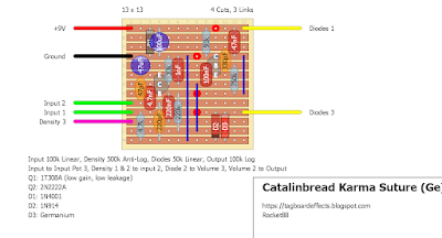
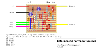
The only change I made in the layout from the schematic is I added a 100uF cap from power to ground to assist in power filtering. Schematic can be found here. Enjoy my fellow fuzzheads.
Catalinbread Karma Suture (Ge)
Catalinbread Karma Suture (Si)
I could never get my home-brewed/imagined versions of this circuit in the ball park of the demos for the karma suture. Stoked to build this one, thanks for posting!
ReplyDeleteI had a reverse polarity question. D1 is positioned 9v to Cathode and Anode to ground. I assume this is an alternative to a series diode with 9v to Anode as a way to avoid the voltage drop?
ReplyDeleteI think D1 orientation on this layout may be an error. Look at the Calliope schematic on Aion FXs website which curiously varies slightly from the one posted on the link above.
Deletethis isn't based on the Calliope pedal, it's based on the schematic of the actual pedal that was created by aionfx as linked in the post. the diode is in the correct orientation as per the schematic, cathode to +9V and anode to ground.
DeleteAh, yes. I get it :) Thanks Zach
ReplyDeleteBuilt the layout as drafted, works great! Thanks again for sharing!
ReplyDeleteThis comment has been removed by the author.
DeleteGe. Used a Russian IT320b ECB tranny @ 50 hFE and a TO-18 2N2222A
ReplyDeleteWill any low gain/leakage PNP Ge do here? 1T308s are pure unobtanium in the UK unless I wanna order a massive boxload from Russia.
ReplyDeleteI'm sure that would work. I'm not as familiar with the markings anymore. Have bought a box or 2 in the past. But not sure what GT308 vs 1T308 vs 1T308s etc is anymore. I live in the Netherlands and could mail you 1 or 2 if you want. But not sure if it's the right ones
DeleteBuilding the Si version here.
ReplyDeleteThere is a pot that is defined as "output", but wiring talks about "volume". These are the same thing right? "Volume 1" is also left floating. Is this correct?
Q1 and Q2 are not specified in the layout, but I suppose the Q1 is at left and Q2 is at right?
Thanks.
All your assumptions are correct!
DeleteHi! I have a problem with Si version. My density and output pots don't do anything. The output sound is pretty high, but the pot doesn't work so I can't change it. Basically, it behaves as a fixed resistor. I double checked solders on veroboard, they are fine. Components are on the right places. Does anyone have any idea what could be the problem?
ReplyDeleteI had the same problem with the output (volume) pot. According to the schematic pin1 fom Volume1 should be wired to ground, not left floating. After wiring pin1 to ground the volume pot worked.
DeleteI have a question about the wiring. The line for "Input to Input Pot 3", does that mean Input 1 from the board to Input 3 on the Pot? And to confirm, Density 1 & 2 to Input 2 on the board? What happens with Density Pin 3?
ReplyDeleteThis comment has been removed by the author.
ReplyDelete