Original thread and schematic available on the FSB forum here.
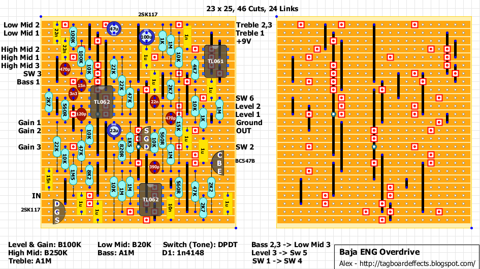
The layout should fit in a 125B box.
09/07/2018 Layout Updated! Inverted Treble and Bass pots' lugs. Changed 390p cap from TL062 pin 5 to 470p. Changed 1K resistor next to 22uF cap to 1K5.
22K resistor between Gain 1 and Gain 3 goes from Gain 1 to 15n/10K 3 rows below instead of Gain 3. 22K above TL062 pin 8 needs to move down one row between 10K/22K and VBias.
looks very interesting thanks Alex for these layouts.
ReplyDeleteOn a side note High & Mid pots are actually High mid and low mid
This comment has been removed by the author.
ReplyDeleteThis comment has been removed by the author.
ReplyDeleteThis comment has been removed by the author.
ReplyDeleteBuilding this one at the moment. I'll finish tonight I just need to get some 1u mkts from work. Looks good so far. The image of the transistor for the bc547 isn't the right way round for the bc547bs i have. It shows the emitter and bass legs are on the opposite side. Not that it should matter if you are checking your pinouts! Its the correct way round for rhe 2n5088/89s and bc550s i have if you are subbing the 547. I'll finish tonight and let you know how it goes!
ReplyDeleteEmitter and collector legs sorry!
DeleteI haven't got mine to work yet I just get oscillation.I've gone over it with a magnifying glass and can't find any obvious problems. I go over it with an audio probe tomorrow and see if i can figure it out.
ReplyDeleteThis comment has been removed by the author.
ReplyDeletePretty much the same as I got with mine. Trashed it in the end... I'd been over everything so many times that I reached a point where I stopped doubting myself and just 'effed it.
ReplyDeleteThe 9V connection should go to pin 7 of TL061. (Same as MDR layout)
ReplyDeleteOps! Well spotted! I've fixed it.
DeleteThis comment has been removed by the author.
ReplyDeleteI just built this and it doesn't work. Even with the missing diode.
ReplyDeleteMDR and Engl schematics are different. No diode here. There were a few easily fixable mistakes in the layout. Compare the new layout with the old one. I've indicated which changes need to be made.
DeleteLet me know if it works.
This comment has been removed by the author.
DeleteThis comment has been removed by the author.
DeleteI have built it and it sounds great!
ReplyDeleteSo, after that last update, and thank to Ryan Chappel, the layout is completely verified?
ReplyDeleteThis comment has been removed by the author.
DeleteThis comment has been removed by the author.
ReplyDeleteYour reviews are serious business, man. What I like that you don't fool around and tell it like it is. By the way, can you recomnend an overdrive pedal to me? I heard this is good: https://bestazy.com/best-overdrive-pedals/ but I need your opinion.
ReplyDeleteCan someone who successfully built this leave its voltages ?
ReplyDeleteMine sounds more like an overdrive, and not a good one !
Thanks !
Just curious, because I was thinking of building this pedal myself.
DeleteDid you add the high gain mod that someone mentioned in the thread on https://www.freestompboxes.org/viewtopic.php?f=13&t=28860???
Temol said this on the forum...
My version of the ENG overdrive. PCB is designed for 1590BB (vertical). For me, there is definitely not enough gain with default schematic values (check frequency response plots to see a difference). So I changed IC1A 8k2 resistor to 15k, IC1B 2k7 to 6k8 and 3n3 to 1n5. This gave me around +10dB (see the graph below).
I also find a tone stack adjustment range quite limited, especially for mids, but I left it as is.
No, I built it verbatim to this layout. I guess there is something wrong on my side considering CleverName verified it.
DeleteOn a side note, I built the Mighty Nut - ENGL Powerball Pre Amp Emulator Lead Channel : https://dirtboxlayouts.blogspot.com/search?q=mighty
It sounds absolutely killer ! Tons on gain
That reminds me I've used an Engl Thunder for years which is a great little rock head and I did a JFET layout for it years ago based exactly on the amp schematic which I think Miro tested. I'll have to dig it out and post it. As it's experimental I'll probably just put it on the forum.
Delete