Here's a collection of vero (stripboard) and tagboard guitar and bass effect layouts that we have put together covering many classic and popular effects in growing numbers. Many of these have been posted on freestompboxes.org, so check that site out for great discussions on building your own effect pedals. Enjoy the builds and please also visit us on Facebook and Twitter
Now THIS one I like. I'll have to wait till my order of NE5534s come in, but I'm definitely building this one. The world needs more low-gain bass overdrives.
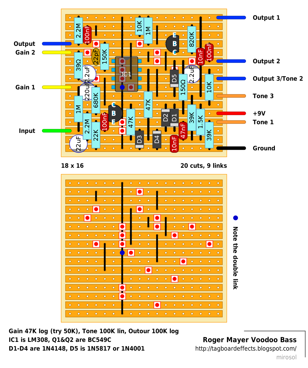
Is Tone 2/Output 3 in the wrong place? The layout has the output on the positive side of the 2.2u cap, but the schematic shows the output after the tone network.
Ok.... I got something working. With the original layout: The Gain pot works, the Tone pot doesn't, and the Volume pot sort of works. The pedal is quiet, significantly less than unity gain, as well as very muffled. I've checked for bad solder joints and bridges, I don't see any.
Output 3 and Tone 2 are on what i like to call "dummy connection". Meaning that those two wires are supposed to connect only to each other. There's a cut before the 2µ2 cap (coming from IC output to tone section).
I sometimes do those "dummy connections" to avoid "tone2 to volume 3" notes, as i personally am against daisy chaining pots.
I checked the layout again against the schematic, and i can't see anything wrong or amiss. Mark?
BTW, the schem i used can be found from FSB: http://www.freestompboxes.org/viewtopic.php?t=14374&p=163919 +m
Of all the things... it was a bad 100K pot. Tag this sucker,and I'm really really really impressed with this one. On low gain settings, it nails that cranked SVT-type sound, and opens all the way up to crazy square-wave fuzz. The tone control is very powerful. An almost perfect overdrive. This plus the modded Zendrive, and I have all my overdrive bases covered. Op-amp was an NE5534, and Q1+Q2 were BC550B.
My thoughts after playing it for a while... I only had 50k linear pots on hand, so I used that for the gain control. I like it a lot and am not going to change it, but I'd imagine those who want to explore the higher gain side of this beast would want to stick with log. I'm actually running this thing with the gain almost all the way off, and the volume wide open, and it makes my 200 watt GK stack sound like a cranked SVT. Next step... 18 volts. Everything for bass tends to sound better at 18 volts.
Just built this one today. IMO, a reverse log 50K pot works ALOT better for the gain control since with the posted log one, the gain doesn't do much from 7 - 2 o'clock and is all bunched up at the end of it's rotation. I changed mine to a C50K and it works a lot better now. I also actually prefer daisy chaining pot wires whenever possible since it allows less wiring from the main board and a cleaner build, plus, if Leo Fender built his amps that way, it's good enough for me. ;-) i also wish that miro's layouts had semi-transparent resistors, diodes and capacitors (like Mark's). IMO, it makes it a lot easier to build and much easier to troubleshoot if you have a problem.
BTW, i ran mine on 9 and 18V and with this one, it didn't make much difference to me at all, so i'm going to keep running it at 9V.
This board's a bit annoying to work with in a 1590B. I did a little bit of a mod to smallify the board. I replaced the transistor input/output buffers with the Timmy gain recovery stage (as the Big Muff tonestack tends to suck signal out.)
http://i.imgur.com/SgQ9jFw.png
With the stock version, I really dig the OPA277 from Burr Brown. It keeps a bit more of the bass's character intact. NE5534's not bad either, a bit grungier.
hmmm. not sure what you mean by 'annoying' to work with in a 1590B', since the board is only 18x16? it's the 22 wide ones that are a tough fit for me. ;-) I tired quite a few different chips in mine (more than 12) and the LM308 was my fave.
I rarely work with 1590Bs, to be honest. Most of my builds are 125B or larger. Not to mention I screwed up one of the drill holes, so I have a bit less room to work with. Anyway, I've built 3 of these, and they're all different. Do you find yours is really fuzzy, even on low gain? I thought I found the perfect bass drive, but now I'm not so sure. I've got my high gain bases covered, but I can't seem to find any low gain drives that I like.
actually the voodoo bass can get almost perfectly clean with the gain knob fully CCW. if yours doesn't then something might be wrong. the wampler Ecstasy, the Cochrane Timmy and the barbershop can all be run clean or low gain and sound great with a bass. and BTW, my barbershop is not modified.
Hi John, I'm building this one for a bass player friend. I'm keen to know if you think the stock cap values are fine or if you would increase them, or perhaps add a split'n blend internally to help preserve the bottom end..?
Newbie here. I've been reading this site for a while now and finally tried to build this as my first pedal. Spent ages on it, plugged in it and...nothing. No sound other than on true bypass. gutted. So can anyone help me please. checked component position and cuts etc all seems ok. Here are my voltage readings.
The gain and tone pot are backwards on this layout. I switched the tone lugs 1&3 and put gain lug 1 from the board to pot lug 3 insted and now it works as it should. I agree that the gain pot should definitly be a C50K. John, did you notice this but forgot to mention it?
I just built this last night and love it, but I can't help but think what changing the clipping diodes and/or IC could do. What IC's can be subbed for the lm308? Anyone one try other diodes, like LED's or change the clipping from symmetrical to asymmetrical? Oh, and Fredrik, I have the same problem with the gain pot, and was thinking about changing gain 1 to gain 3 and seeing if that fixes it. Glad to know that's the cure.
Just finished this for my nephew. Sounds great, you could easily use this on guitar as well. Definitely want to use the C50K reverse log pot on the gain as mentioned before. Without that, 90% of the gain is bunched up in the last 10% of the knob sweep. I will post a pic soon, as the box is still drying. Thanks guys.
I guess the 1.6M feedback resistor from the voodoo one is missing. Original pcb layouts on Reverb shows 1.6M resistor connecting two transistors, both on VD1 and VD BASS. The pedal sounds good anyways, but gets too bassy (treble gets removed). Maybe feedback resistor might cure.?
Now THIS one I like. I'll have to wait till my order of NE5534s come in, but I'm definitely building this one. The world needs more low-gain bass overdrives.
ReplyDeleteBuilding this now, I've noticed one issue so far. The top lead of the 820K resistor goes into a track cut. I've moved the resistor one row over.
ReplyDeleteI'll check it through today...
DeleteSeems ok - removed the link, as it did nothing in there. Maybe a leftover from the Voodoo1...
Delete+m
Yup. That cut is needed in Voodoo1, but not in this one.
DeleteI have a request.... Roger Mayer Page-1
ReplyDeleteIt's possible?
Thanks in advance
Is Tone 2/Output 3 in the wrong place? The layout has the output on the positive side of the 2.2u cap, but the schematic shows the output after the tone network.
ReplyDeleteOk.... I got something working. With the original layout:
DeleteThe Gain pot works, the Tone pot doesn't, and the Volume pot sort of works.
The pedal is quiet, significantly less than unity gain, as well as very muffled.
I've checked for bad solder joints and bridges, I don't see any.
Output 3 and Tone 2 are on what i like to call "dummy connection". Meaning that those two wires are supposed to connect only to each other. There's a cut before the 2µ2 cap (coming from IC output to tone section).
DeleteI sometimes do those "dummy connections" to avoid "tone2 to volume 3" notes, as i personally am against daisy chaining pots.
I checked the layout again against the schematic, and i can't see anything wrong or amiss. Mark?
BTW, the schem i used can be found from FSB: http://www.freestompboxes.org/viewtopic.php?t=14374&p=163919
+m
Of all the things... it was a bad 100K pot. Tag this sucker,and I'm really really really impressed with this one. On low gain settings, it nails that cranked SVT-type sound, and opens all the way up to crazy square-wave fuzz. The tone control is very powerful. An almost perfect overdrive. This plus the modded Zendrive, and I have all my overdrive bases covered.
DeleteOp-amp was an NE5534, and Q1+Q2 were BC550B.
Thanks Ross! Great thing it fired up!
Delete+m
My thoughts after playing it for a while...
DeleteI only had 50k linear pots on hand, so I used that for the gain control. I like it a lot and am not going to change it, but I'd imagine those who want to explore the higher gain side of this beast would want to stick with log. I'm actually running this thing with the gain almost all the way off, and the volume wide open, and it makes my 200 watt GK stack sound like a cranked SVT. Next step... 18 volts. Everything for bass tends to sound better at 18 volts.
Just built this one today. IMO, a reverse log 50K pot works ALOT better for the gain control since with the posted log one, the gain doesn't do much from 7 - 2 o'clock and is all bunched up at the end of it's rotation. I changed mine to a C50K and it works a lot better now. I also actually prefer daisy chaining pot wires whenever possible since it allows less wiring from the main board and a cleaner build, plus, if Leo Fender built his amps that way, it's good enough for me. ;-) i also wish that miro's layouts had semi-transparent resistors, diodes and capacitors (like Mark's). IMO, it makes it a lot easier to build and much easier to troubleshoot if you have a problem.
ReplyDeleteBTW, i ran mine on 9 and 18V and with this one, it didn't make much difference to me at all, so i'm going to keep running it at 9V.
I also want to add that I love the sound of this one. thanks Miro!
ReplyDeleteThis board's a bit annoying to work with in a 1590B. I did a little bit of a mod to smallify the board. I replaced the transistor input/output buffers with the Timmy gain recovery stage (as the Big Muff tonestack tends to suck signal out.)
ReplyDeletehttp://i.imgur.com/SgQ9jFw.png
With the stock version, I really dig the OPA277 from Burr Brown. It keeps a bit more of the bass's character intact. NE5534's not bad either, a bit grungier.
hmmm. not sure what you mean by 'annoying' to work with in a 1590B', since the board is only 18x16? it's the 22 wide ones that are a tough fit for me. ;-) I tired quite a few different chips in mine (more than 12) and the LM308 was my fave.
Deletehttp://johnkvintageguitars.homestead.com/Effects/Fuzz-ODs/VoodooBass/VoodooBass-01.jpg
I rarely work with 1590Bs, to be honest. Most of my builds are 125B or larger. Not to mention I screwed up one of the drill holes, so I have a bit less room to work with.
DeleteAnyway, I've built 3 of these, and they're all different. Do you find yours is really fuzzy, even on low gain?
I thought I found the perfect bass drive, but now I'm not so sure. I've got my high gain bases covered, but I can't seem to find any low gain drives that I like.
Disregard that. I heard your clip of the Barbershop. Absolutely astonishing. Did you mod it for bass? If so, how?
Deleteactually the voodoo bass can get almost perfectly clean with the gain knob fully CCW. if yours doesn't then something might be wrong. the wampler Ecstasy, the Cochrane Timmy and the barbershop can all be run clean or low gain and sound great with a bass. and BTW, my barbershop is not modified.
DeleteHi John, I'm building this one for a bass player friend. I'm keen to know if you think the stock cap values are fine or if you would increase them, or perhaps add a split'n blend internally to help preserve the bottom end..?
Deleteit doesn't need any mods for bass (has no low end loss) and, IMO I don't think it needs a blend either.
DeleteAwesome, thanks for that. Thanks for the vero Miro
Delete+1 on the 50k reverse audio drive pot!
DeleteHi guys.
ReplyDeleteNewbie here. I've been reading this site for a while now and finally tried to build this as my first pedal. Spent ages on it, plugged in it and...nothing. No sound other than on true bypass. gutted. So can anyone help me please. checked component position and cuts etc all seems ok. Here are my voltage readings.
Supply: 9.22V
At board: 9.22V
Q1 (on left)
C: 4.56V
B: 1.3V
E: 0.82V
Q2 (top right)
C: 7.61V
B: 3.38V
E: 2.91V
IC
P1: 6.95V
P2: 5.15V
P3: 4.55v
P4: 0V
P5: 0V
P6: 6.91V
P7: 7.63V
P8: 5.87v
D1:
A: 0V
K: 7mv
D2:
A: 3mv
K: 2mv
D3:
A: 7mv
K: 0V
D4:
A: 0V
K: 9mv
D5:
A: 8.25V
K: 7.61V
Thanks in advance.
Paul.
I just built this one. It sounds great!
ReplyDeleteThe gain and tone pot are backwards on this layout. I switched the tone lugs 1&3 and put gain lug 1 from the board to pot lug 3 insted and now it works as it should. I agree that the gain pot should definitly be a C50K. John, did you notice this but forgot to mention it?
cheers
Thanks for the layout!
I recall others building this too and none of those mentioned it... I guess i kshould double check, but it'll be a while.
Delete+m
Yes they are.. both gain and pot are backwards
DeleteI just built this last night and love it, but I can't help but think what changing the clipping diodes and/or IC could do. What IC's can be subbed for the lm308? Anyone one try other diodes, like LED's or change the clipping from symmetrical to asymmetrical? Oh, and Fredrik, I have the same problem with the gain pot, and was thinking about changing gain 1 to gain 3 and seeing if that fixes it. Glad to know that's the cure.
ReplyDeleteJust finished this for my nephew. Sounds great, you could easily use this on guitar as well.
ReplyDeleteDefinitely want to use the C50K reverse log pot on the gain as mentioned before. Without that, 90% of the gain is bunched up in the last 10% of the knob sweep. I will post a pic soon, as the box is still drying.
Thanks guys.
And the finished box....my nephew calls me Unky.
ReplyDeletehttp://i892.photobucket.com/albums/ac124/digthebigrigg/UnkyDrive_zps54ca9b0b.jpg
Just built this. Works great. Thanks!
ReplyDeleteI guess the 1.6M feedback resistor from the voodoo one is missing.
ReplyDeleteOriginal pcb layouts on Reverb shows 1.6M resistor connecting two transistors, both on VD1 and VD BASS.
The pedal sounds good anyways, but gets too bassy (treble gets removed). Maybe feedback resistor might cure.?