Sorry for such a long delay in publishing some new layouts, there's been a lot of changes going of for me which has taken up a lot of my time to sit and make some new layouts. Shortened version: became a doctor, had my first child with my wife, got a new job practicing, lots of home projects around the house, and COVID. Here's the first of many new ones from me coming at you. Figured I'd start with something familiar to all the fuzz lovers out there, as you can never have enough muffs.
From the Source:
The Cloven Hoof is an extension of Earthquaker Devices popular Hoof fuzz, only more… cloven. Earthquaker kept the clarity of the Hoof along with the wide range of dirt tones and redesigned everything around it. The Cloven Hoof delivers a grittier, more bass heavy tone with more crunch that can not be achieved with the standard Hoof. They did away with the germanium transistors and replaced them with 4 specially selected silicon transistors for higher gains, cleaner cleans and improved temperature stability. The fuzz control has four times the range of the regular Hoof, it will go from completely clean to an all out fuzz fury with more grind at the top end of the dial. The tone control has been refined to allow a more even sweep with enough mids to handle all the additional low end. The shift control still boosts or cuts the mids and there is still a TON of output on tap. The Cloven Hoof is the perfect solution for those of you who always wished the Hoof had more. Each Cloven Hoof is made by hand in the majestic mountain top village of Akron, Ohio.
Controls
Fuzz: Clockwise for heavy, counterclockwise for light.Tone: Bass to the left, Treble to the right.
Level: Use this control to make the Cloven Hoof louder or quieter.
Shift: This adjusts the mid content, clockwise for scooped mids, counterclockwise for boosted.
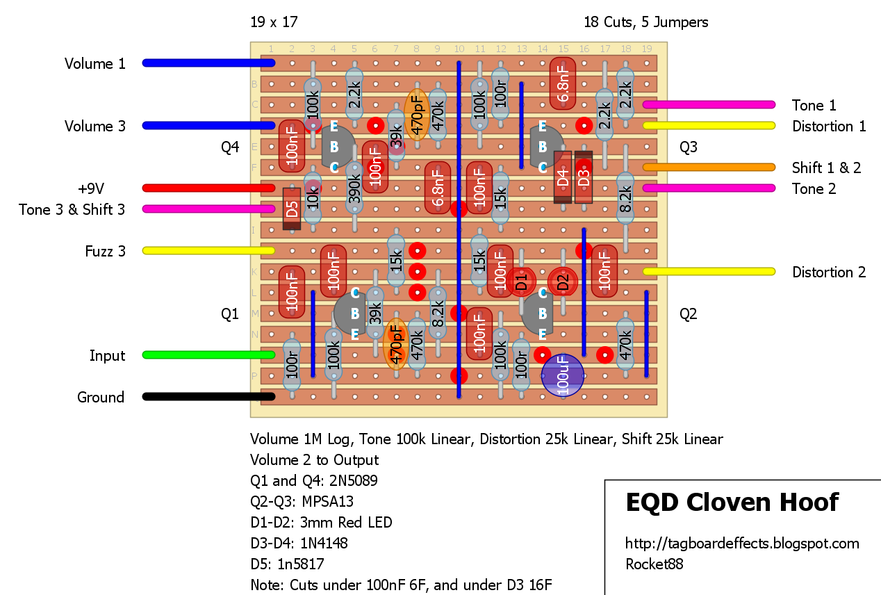
Which transistors are which on the layout?
ReplyDeleteupdated with lables
DeleteCongrats for all that !
ReplyDeleteNice to see you back also !
Congratulations!
ReplyDeleteHey, congrats on all that!! Perfect timing also, was just looking for a good fuzz build for this weekend :)
ReplyDeleteDon't have the 2N5089 laying around, so I'll socket those and update here. Any advice on good possible substitutes?
2N5089’s are high gain Silicon transistors, so you can experiment with similar spec transistors, just watch for pin out changes.
DeleteI just completed mine with a pair of 2N5088s. Sounds awesome; gnarlier than the regular Hoof in a side by side, so I guess they're getting the job done.
DeleteWelcome back, and congratulations doctor. It always makes my day when I open the blog and there is a new layout. Thanks heaps
ReplyDeleteBloody hell, congrats on the child and doctor-becoming! That's one hell of a good reason to be busy!
ReplyDeleteThis also looks like it's all common parts, so I might actually give it a go, looks fun!
Congrats, on everything, and thanks for finding the time to post this project. Can we use 2 general purpose NPN transistors in a darlington configuration in place of the MPSA13s?
ReplyDeleteFrom one doctor to another, congrats!
ReplyDeleteZach, Congrats on everything!!! And thanks for this layout, great job. Just finished and played for about 30 minutes on the bench. All the controls work as expected. This one sounds really lush with tons of sustain. Was just thinking about looking for another muff and what, there is a new layout posted, and its a muff!! Thanks man!
ReplyDeleteGreat! Thanks a lot!
ReplyDeleteCongratulations Zach! On everything. From following it from afar here I know how much work it has been always being busy with your papers. That's quite the achievement!
ReplyDeleteHi, I don't have MPSA13. Can I use 2n222 instead?
ReplyDeleteYou could always socket it and try it, but an MPSA13 is a darlington transistor with extremely high output compared to a 2n2222
DeleteThank you for answering RedSolution.
DeleteDo I have to use a specific transistor to recreate the MPSA13 in a Darlington configuration?
This comment has been removed by the author.
ReplyDeleteHello everyone, obviously I didn't know about Darlignton configuration. Can anyone tell me what's the best transistors to use in a Darlignton configuration to emulate the MPSA13?
ReplyDeleteIf I'm wrong again please let me know. Thanks.
Congratulations mate, I'm made up for you!
ReplyDeleteHey, congradulations! Huge big steps in life. Things to look forward to: during COVID I got two of my kids (ages 5 and 8) into pedal building!
ReplyDeleteSo this is my second pedal and have some questions.
ReplyDeleteWhat are the red dots?
wehre is the output supposed to go?
also hod connect the power on led and the switch?
only realized i ad these questions after i was half way to the pedal
The red dots are cuts in the copper track on the back of the vero board. Output is Lug 2 of the Volume pot (listed in the layout notes). As for the offboard connection take a look here https://tagboardeffects.blogspot.com/2012/02/offboard-wiring.html
DeleteHope that helps some
Hello, I am new to this world. I have obtained all the components indicated by the design. But I have several problems. I don't know what type of cable to use to make the bridges. I also don't know where to place the external cables (volume1,3; tone1, 2, 3, etc ...)
ReplyDeleteI hope you can help me.
A greeting from Spain.
You can use the cut off leads of resistors to make the links or bridges or 22 gauge solid wire. For the external wiring here is some guides to aid you: https://tagboardeffects.blogspot.com/2012/02/offboard-wiring.html and https://tagboardeffects.blogspot.com/2012/04/vero-build-guide.html
DeleteThank you very much but I still don't understand where each wire has to go. the example in the guide is very simple. I made it and everything is correct. But this other one seems very complicated to me. could someone teach me. If anyone can send me a video tutorial I would really appreciate it.
Deletechamber10studio@gmail.com
DeleteHey, congratulations on your new role as a doctor and a dad!
ReplyDeleteCongrats, great to hear the good news and have you back!!!
ReplyDeleteCongrats! Zach!
ReplyDeleteBecoming a doctor and a dad, and posting a new veroboard, how can you be happier!
Congratulation Zach on both your new roles. And thanks a lot for posting this layout.
ReplyDeleteI know you would have your hands full right now but if someone here can please help me with a query it would be much appreciated. Does there need to be an additional 470pf cap between Base-Collector of Q2? Thanks.
Hi, I just finished the pedal and it doesn't work. The led sometimes lights up and sometimes it doesn't. When activating the pedal the guitar stops being heard. When you deactivate the pedal, the guitar will sound again. Why can this be? Thank you
ReplyDeleteI've spent 50 hours on this and is still just a complicated bypass.
ReplyDeleteIt doesnt change the sound at all any idea?
This comment has been removed by the author.
ReplyDeleteThis comment has been removed by the author.
DeleteHi, I'm starting with DIY pedals, have a pair of questions:
ReplyDelete1. The 100uf blue condenser is non polar electrolytic?
2. What's the difference between the red and orange (470pf) capacitors?
Thanks
We must be in the same boat. I was wondering that myself so I did a little research.
DeleteThe color difference means nothing. Just a different way to display them. I did this by reading older posts and things about vero board layout.
The 100uf blue capacitor is indeed bipolar. If it wasn't it would have a - signifying negative. Don't confuse yourself like I did, get in the habit of saying bipolar instead of non-polar. They have to have polarity one way or the other. Good luck!
You could also use a polarized capacitor for the 100uf as you can clearly see that one side goes to ground on the board. The cathode (neg) side of the capacitor goes towards ground.
Thanks Wynn, I realy appreciate your help ✌
DeleteJust saw this, but it is polarized. Negative towards the bottom. On these layouts you can tell which side is negative because it is shaded gray.
DeleteAnyone have the schematic for this pedal
ReplyDeleteTrying to troubleshoot. Are the LEDs inside supposed to light up with signal?
ReplyDeleteMpsa13 to mpsa18? Is it possible?
ReplyDelete