Guitarists of all styles will dig the familiar late-Sixties/ early-Seventies crunch delivered by the new MXR Classic 108 Fuzz. We've taken the guts of our BC-108 loaded Fuzz Face, placed them in a more pedal-board friendly shape, and added the modern conveniences of a battery door, optional AC operation, and true bypass with LED. The Buffer switch eliminates the audible oscillation caused when some wah-wahs are placed in front of a Fuzz Face. The Classic 108 Fuzz comes in a heavy-duty Phase 100-sized box with a sweet hammertone turquoise finish.
And here is the buffer for people who want to build the whole thing.

Haha! I would swear profusely here! ... I'll still make one though mate as it's a pretty small build and I can a/b it with mine and if it stacks up well, I'll just sell on the original. I'd definitely recommend one though..fantastic fuzz...both knobs cranked and it's bliss..
ReplyDeleteWell I did tell you I was going to do it! :o)
DeleteIt's cool.. I didn't mind buying it as the buffer is really good in it too... Is there a close alternative to the 5r1? near on impossible to find here
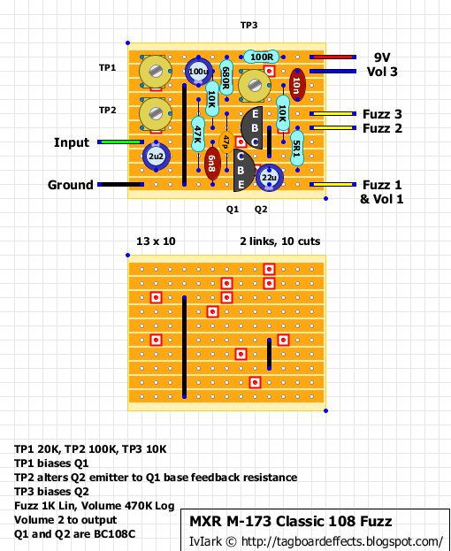
DeleteUse the lowest value you've got. It's one of the anti oscillation measures we were talking about the other day and I've done it with 47R or 100R (can't remember which) in the past.
DeleteI've got lots of different types that can fit in a variety of spans including vertical and horizonal, but these are the ones I have in the greatest quantities:
ReplyDeletehttp://www.ebay.co.uk/itm/290716067907
http://www.ebay.co.uk/itm/330816589594
The first ones in particular are good for smaller spaces like with this layout, but they both have the required 5mm pitch distances.
Alps RH06's are really great too. They too have 5mm pitch distances, but the outer legs are about an inch long so you can use them for any span. Very useful for resistor replacements to bias without having to do a special layout to accomodate trimmers.
Oh and yes the trimmers are in the original.
ReplyDeleteWill BC108b work for this?
ReplyDeleteYes they're just in a lower gain range. Socket and experiment to get your favourite pair.
DeleteI haven't messed with buffers before. Will the Klon one you posted (http://tagboardeffects.blogspot.com/2011/04/klon-buffer.html) do the job? And just connect the boards via a switch? Thanks
ReplyDeleteTo be honest I just don't know. Like in a normal chain the Fuzz Face may not react well to a buffer in front of it, so it's a case of try it and see. That's why I haven't just included a buffer of my choice in the layout, because it just may not work properly. When Vince has received his we may coerce a few high res gut shots out of him and hopefully be able to come up with the buffer from that.
DeleteThat won't be a problem...When it arrives, I'll snap some pics.
DeleteTop man
DeleteI've not forgotten the pics mate, I've had to send off for a new battery for my camera...I'll get them done ASAP.
DeleteCheers matey
DeleteWhat A great sounding Fuzz. Really gets that Gilmour "Time" Solo tone.
ReplyDeleteDoes anybody get that strange behavior that the fuzz sounds kinda weak throughout the clock on the fuzz knob and then when you reach the max the fuzz really gets sharp and penetrates your guts?
Did you build it from this or have you got an original?
DeleteIf you're talking about the original then yes, the fuzz control does act that way... I keep it cranked and use the guitar volume. Thats the geat thing about this one, cleans up brilliantly.
DeleteThats where the buffer is useful, It gives the fuzz a bright kick on lower settings.
I'm waiting on some 680r's then I'll definitely make one, purely out of curiosity ;0)
Thanks for the comments,
DeleteWell I built a similar one which does not include trim pots but a 33k for TP1, 100k for TP2 and a pot for TP3 for biasing Q2. I used BC108C and I did NOT use the buffer section. The output pot was also lower.
I did use a 50k pot for the input to get lower input but that's not a buffer. What parts are the buffer?
the 6n8 cap and the 47k res? What is the function of this 47k?
Thanks
The 47K is in series with TP2 and sets a minimum value. So with that trimmer you can alter the value from 47K to 147K, for what is usually a 100K resistor and so it offers a nice range of tweaking.
DeleteThe only thing I'm dubious about is that the feedback resistor in the classic Fuzz Face is at the transistor side of the 2u2 cap, and so would come from the base of Q1 rather than directly from the input wire row. That is definitely how it is shown on the schematic, but whether it's an error I'm not sure because the guy who did the scheme never answered the question when asked. If it doesn't work though that's the first thing I'd look at, 47K and 47p coming from Q1 base rather than the connections shown.
Any chance of posting the schematic of this one?
DeleteThe more I look at it the more differences I find from the good ol' Silicon Fuzz Face like the Axis Face by Bryant or the GGG Silicon Fuzz Face. Maybe it's closer to the SunFace?
I am drawing a schematic according to the layout but if anyone beats me to it....please share link...
Thanks
http://freestompboxes.org/viewtopic.php?f=1&t=2842
DeleteOK....got the schematic from the Freestompboxes forum.
DeleteExcept for a few value changes, the main difference from a regular Fuzz Face is the way the feedback resistor between Q1 and Q2 is placed. As you said Mark, On the MXR it's before the input cap where as in the original designs it's after the input cap.
Definitely makes me wonder and probably behaves somewhat differently.
I've had no joy with this mate. I used a 10r in place of the 5r1 and used BC108C's (tried many). Funny thing is, is it that something is working. If i press the back of the board I get a fuzz signal now and then.. I've also tweaked all trimpots in all positions. I've reflowed all joints etc so I really don't know. could be my build. Hopefully someone will have better luck with it.
ReplyDeleteBefore you ditch it, I'm still unsure about the connection shown for the feedback resistor(s) in the schematic. Remove the 47K and 47p and solder their bottom leads into the second from bottom row between the 6n8 and link. See if you can cram both into the same hole with their top leads going to the same places (Q2 emitter for the 47p and top lug of TP2 for the 47K).
DeleteThat is how a conventional Fuzz Face would connect so it would be interesting to see what happens.
Ok, I'll try that later mate and post back ;)
DeleteI've done that and I get the same results. If i place my finger over the 2u2 cap, shorting it around there, I get 'fuzz' not great sounding but there is something happening. It looks like others are attempting it so hopefully someone will get back with success. I'm once bitten twice shy, especially when it comes to Fuzz faces ;)
DeleteI just noticed that the trimmer graphic could be interpreted as being in virtually any orientation (I'll have to alter that). You have both got the wipers for all the trimmers to the right haven't you?
DeleteYes, all trimmers are pointing to the right.
DeleteWhat high and low voltages are you getting at the top of the two 10K resistors when you rotate each associated trimmer?
ReplyDeleteOK you replaced one with a link, but you know what I mean! :o)
ReplyDeleteWhat voltage are you getting at both sides of the 100R?
ReplyDeleteSomething has to be wrong with the trimmers then. In the fully counterclockwise rotation of TP1, it effectively attaches the top of the 10K directly to the supply rail and so you should be getting close to 9.27V. In the clockwise rotation it puts 20K of resistance in the way and so you would expect less. Same issue with TP3 but at slightly lower voltages because of the 680R resistor. The higher voltage will be in the clockwise position for TP3 though. So TP1 fully CCW and TP3 fully clockwise should be giving you close to thefull supply voltage at the top of the respectiev 10K resistors.
ReplyDeleteYour voltages in your previous post look good, the 0.77 to 1.12 at the other end of the 10K looks too much of a drop to me. Have you tried any other transistors, just in case that is pulling it down?
ReplyDeleteYup. Check the FSB-thread, commit a fix and tag it :)
ReplyDeleteRavian: Desolder the bottom lead of 47K resistor and wire it to the Q1 base instead of the input.
This makes a nice blue-face alternative. I used B500K pot for the volume and subbed the 5R1 with 7R5. If i was to rebuild this, i would go with C1K for fuzz pot. For transistors, i went with BC108B for Q1 and BC108C for Q2.
I always shout out that "Do not take bias control outside the box!" - but this time that could be something to think about. Seems that you can't break it with those three trimmers :) Might have something to do with them being relatively high gain silicons..
Anyway. Once fixed, it's a nice fuzz.
+m
Awesome, nice one Miro
Deletehi i want some information about trimmers biasing q1,q2 and feedback what are the voltages i must have?
ReplyDeleteThis comment has been removed by the author.
ReplyDeleteFuzz Faces are tricky beasts, but I can say I got this one working. It's still a bit gated (I didn't match the transistors), but it's not bad at all. It remains articulate on chords, which I like, and sort of gets the Eric Johnson violin tone up the neck. However, I still prefer the Meathead. Transistors were my favorite mid-gainers (BC550B).
ReplyDeleteI forgot to mention the mods: I call it the "I'm way too lazy to get trimpots" mod.
DeleteThe 47K resistor gets upped to 120K, and the top lead gets moved down a row so it connects the emitter to base
The 10K bias resistor gets upped to 22K, and the top lead gets moved up a row to +9V.
The only trimpot I used in the build was the 10K to bias Q2, and that's really important.
Hi thanks for your amazing work!
ReplyDeleteDoes your vero permits to build the buffered version of this fuzz?
Thomas
You could take any buffer from the library and use the dual effect outboard wiring guide. Just take the buffer stompswitch and replace it with a toggle. You could also omit the LED from that switch.
Delete+m
Is there any information on how to properly bias? Or is is best to do it by ear?
ReplyDeleteTune it by ear. With Si BJTs (bipolar junction transistors) i've found that to be the best course of action. They will work with almost any setting, but affect the texture of the fuzz - While JFETs and Ge BJTs usually need just the right bias voltage to work properly.
Delete+m
I revisited this and built it again, The fuzz section sounds good, the buffer seems to introduce a fair amount of hiss, it does what it is supposed to though, taking a wah pedal better but with the wah and buffer on it is extremely hissy, I can't remember it being like that on my original. I did have them in separate test boxes though so that may have contributed to it. I also tried running it through the Klon buffer instead and it sounded terrible, like it was badly biased so I don't think it's an 'any buffer will do, type of design...
ReplyDeleteHi! Is there a transistor I could use in the buffer instead of the MPSA14? Tayda does not have them and I can't seem to find any in my area. Any ideas?
ReplyDeleteHi, Need I change some position component in the stripboards? Are there any fixes yet to be made? Thanks
ReplyDeleteAlthough this has been verified already, I also would like to do that as well. It works perfectly and its fun to play with. Thanks for your effort! :-)
ReplyDeleteOne personal recommendation: Matched transistors help very much. I bought a lot of BC108C and B108B, measerung them and tried several. Eventually I ended up with a pair of BC108C.
What I like the most: This effects works very well with volume pot of my guitar.
When boxing this up is the buffer supposed to go before, or after the fuzz circuit?
ReplyDeleteI'm late to the party: Surely the 10K leading to Q2 collector is an error. Normally a fuzz with a 1K fuzz pot would have around 8.2K going to Q2 Collector. I recon someone misread the code on the resistor and its actually meant to be a 1K, then the trim for Q2 would bias about half way through its travel (I'm guessing at around 5K to get 5V or so given relatively standard settings for the other trims - starting at a total of 33K for Q1 and a 100K feedback resistor)
ReplyDelete