Here's a collection of vero (stripboard) and tagboard guitar and bass effect layouts that we have put together covering many classic and popular effects in growing numbers. Many of these have been posted on freestompboxes.org, so check that site out for great discussions on building your own effect pedals. Enjoy the builds and please also visit us on Facebook and Twitter
Here is a very nice project by Dschwartz from the DIY Forum.
You can find the original thread here
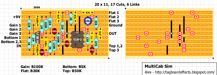
13/01/2017 Layout updated! Change 4n7 cap connected to Flat 1 to 47n.
Wow, cool stuff and super interesting thread. I think i'll give it a try next couple of days. Best thing is, that this will cost almost nothing, cause I got every part on stock. But I think I'll try a diffrent OP-amps and transistor. Thanks for posting!
tudo bem nico lohse! Gostaria de saber como ficou seu projeto, pois entereceia na ideia de mudar o CI e Transistor, poderia nos expor como ficou o pedal?
I built this last night. It is verified except the Top pot is reversed. I have been playing it all morning with my Pinnacle (high gain Marshall) pedal into my recording mixer and through my studio monitors. This is really a nice cabinet sim. Unlike most it has a ton of gain. The Flatness control really makes it come alive. I will label this control Focus on my build instead.
Yes it is active and capable of boosting/cutting bandwidths, but don't think of it as a tone control. It is a set of interactive filters designed to duplicate the EQ curves imparted by various speaker cabinets. It also will give you the impression of a microphone being swept around on the speaker so you can find a "sweet spot" for each signal.
If you want something for the end of your signal chain going into an amp, try the tonemender or the Anderton super tone control builds on this site. You will be very happy with either of those.
Can anyone explain what the different pots do in layman' terms? Are the just treble mid bass and volume? Or is there on that corresponds to mic placement, one to can type, etc. If the former, does anyone have suggested settings for a Marshall 4x12, for instance, or a fendery 1x12. My ears aren't the best trained to pick out those speaker freq curves but I know them when I hear them. Dialing in is always hard for me tho. I'll be playing straight off my pedal board into a mixing board then a headphone amp.
The gain control is your level. The main action comes from the Flat control. The Top and Bottom are narrow filters that are interactive to a degree with the flat knob. In use, I can not say "to get a certain cabinet you need this setting". I can say you will transform a brittle sterile distortion tone into something much more usable and recordable. As far as copping exact cabinet details like a 1992 mesa 4-12 or a vintage Marshall cab I do not approach this build in that manner. Though I have used many many cabs in my years I do not hear any identifiable nuance to say it sounds like this or that. I can say it sounds very good! This sim will bring an edge and definition and punch to your tone.
Start off by setting your distortion's output level so that it does not distort the cab sim's input. Just crank it up and listen you will hear the spot where it happens. Stay well below that level. Now, set the Gain on the cab sim to 9 o'clock (unity) and the Top and Bottom at 12 noon Flat at 0. Have someone play your rig so you can twiddle and start by cracking open the Flat control until you hear the sound start to come alive or open up. Stop there and tweak the Top and Bottom controls to fine tune what you have. Take your time and use the Flat control to get in the ballpark where you want to be. That is the control that sounds much like sweeping a live mic around on the speaker to find a sweet spot.
Best results come not from listening to the guitar tone all on it's own, but with the guitar sound in the mix where you can really define a position within the other instruments.
I'd love if this thing had a stereo headphone amp. I found one out there but was kinda complicated to build so just going to run it through my mixing board fir now.
Hello Alex, is there any difference between this Multicab sim and the one posted here? http://www.aerhalev.net/alex/multicabsim_final.jpg - I was building the old one and now i dont know if is worth to finnish it. Any help please :)
ANybody? If you could just post what the proper voltages are, that would be helpful too. Then maybe I could figure out where things are going wrong. Thanks.
Question - there are small red caps marked as 220n and 100n - but they appear in the diagram like they should have been labeled 220p and 100p (based on how they look); so, are they "n" or "p"?
I built this using P for these parts, and I have less than unity gain, so I am guess it is the other way around. I am just curious why they were made to look like pF caps if the are really nF?
Hi Paul. All my layouts are the same. If the yellow caps span just 2 rows instead of 3 you can't read the values. That's why I use red caps in that case. Just for practical reasons. The values are the important part, not the color of the caps.
I'm looking for a cab sim more prone to cleaner sounds- or cranked fender sounds (i'm gonna use a few amp in box pedals, but nothing high gain) along with my damage control tube preamp. I read that this distorts on its own... is that correct? do you guys think that I can dial in some good sounds for typical blackface style cabs? or is it all celestions and whatnot? Thanks!
Ahoy, I am getting less than unity gain, actually I m getting quite a bit of attenuation..
Found a mistake, the 4.7n horizontal cap in the first line should be 47n! Moreover, the 100n cap between 9V and ground is not in the original schematic, I assume you put it there for extra filtering?
γεια σου φίλε! yeap. you're right about both! it should be 47nf, and the other is for extra filtering. if you're reading the forum, i'm about to build a modded one. so i could use your oppinion on how it sounds when you'll make it work properly..chhers
Ahoy ξεναγέ! So I corrected mine and indeed it sounds more reasonable now.
The volume drop, even with all the controls to 11 is still below unity though and I have triple-checked everything... Given the way that it interacts with other pedals, I am suspecting that the input impedance might be very low due to the BJT transistor. Maybe we should redesign the input so as to use a JFET.
Anybody else experiencing less than unity or is it just me? I also tried a 2n2222 in the place of the 2N2394 but nothing changed.
Alex? Anyone? Which schematic are you planning to use ξεναγέ and what are you bound to change? Thanks!
Oh, the coming of age and the carelessness of the youth combined... The infamous "one hole down" error struck again, good thing i slept over it and found it... I must not be working on circuits when I m tired :) So, gain fixed, I hope I was fast enough not to cause any trouble.
Yet, the 4.7n upper horizontal cap error on the vero should be corrected to its proper value (47n) :)
Hi! Built This last Night, I have a really tiny sound, really not enough volume and no bass. The led don't work too, but I think it comes from it. Any help ? thx !
Fixer the output volume ! I change the initial 100nf cap with à 47pf. But the bass problem still here. I have ni control on It. I connected the bottom 3 on lug of bottom 2, and This one on the board. Is the bass control is really narrow ?
Built two of these thus far, with a third to follow this week. Such a fantastic tool to have on a pedal board! Mine was built pre changing the first horizontal cap and works as well as I need it to. Will be interested to hear the difference when the third is built which will include the most recent revision above. Brilliant brilliant pedal Alex!
Hi guys ! After verifying the resistors, I have the 120k measured at 107.5k and the two 100k began at 37k ans increase to 67k. The effect was out of power. Someone have already saw that?
Did anyone try to record with this one? I ve been using it with a mixer with no problem. When we try to record directly on the sound cards' input, there is some bassy grit (even with the gain set very low)
Can I place this effect on line out or send out from amp (means after preamp)and run it directly to mix instead using micking the speaker? Will it work? Thanks
After preamp - Yes you can Run directly to mix - No, since impedance isn't matched. You may get away with this using a DI box to convert it instrument level input to line input.
Hello, Just built it. But, the bottom pot cuts pretty much low end. On top of that there's a constant noise like the motor of a boat puffing along. When I remove the bottom potmeter, i get decent low-end and the noise is almost gone.
Update: Just soldered all the pots directly to the board. I had them on the breadboard for testing. Low-end loss is gone but the weird noise stays and is more pronounced when turning the bottom-potmeter
Hi, just want to say I built this for my bass rig and it works great. I added a switch to put a bigger cap (~10uF maybe? I forget now) in parallel with the rightmost 4n7 to simulate a closed cab. Sounds great on bass with this engaged, and didn't require any changes to the layout.
Hi, maybe anyone can help add headphones out to this cab sim? Or maybe there is some schematic for headphones. I've made a while ago MXR headphone amp and it sounds very "sandy". So now i'm wandering if this will work well if i chained it as Guitar -> FX pedal -> MultiCabSim -> MXR Headphones amp?
Wow, cool stuff and super interesting thread. I think i'll give it a try next couple of days. Best thing is, that this will cost almost nothing, cause I got every part on stock.
ReplyDeleteBut I think I'll try a diffrent OP-amps and transistor.
Thanks for posting!
tudo bem nico lohse! Gostaria de saber como ficou seu projeto, pois entereceia na ideia de mudar o CI e Transistor, poderia nos expor como ficou o pedal?
DeleteAny chance you post the Bass version missing from the site? Thank you very much. Great work!
ReplyDeleteSorry but I don't have the bass version.
ReplyDeleteI built this last night. It is verified except the Top pot is reversed. I have been playing it all morning with my Pinnacle (high gain Marshall) pedal into my recording mixer and through my studio monitors. This is really a nice cabinet sim. Unlike most it has a ton of gain. The Flatness control really makes it come alive. I will label this control Focus on my build instead.
ReplyDeleteThanks Al!
DeleteI've changed it.
Is there anything stopping me putting this at the end of my effects chain and then into a clean valve amp?
ReplyDeleteThis comment has been removed by the author.
ReplyDeleteIs the tonecontrol (b.,m,t) working passiv? Or does it boost too?
ReplyDeleteYes it is active and capable of boosting/cutting bandwidths, but don't think of it as a tone control. It is a set of interactive filters designed to duplicate the EQ curves imparted by various speaker cabinets. It also will give you the impression of a microphone being swept around on the speaker so you can find a "sweet spot" for each signal.
DeleteIf you want something for the end of your signal chain going into an amp, try the tonemender or the Anderton super tone control builds on this site. You will be very happy with either of those.
Thanks Al.
DeleteThank for the recommendations Al. I'll have a look for them for sure
ReplyDeleteCan anyone explain what the different pots do in layman' terms? Are the just treble mid bass and volume? Or is there on that corresponds to mic placement, one to can type, etc. If the former, does anyone have suggested settings for a Marshall 4x12, for instance, or a fendery 1x12. My ears aren't the best trained to pick out those speaker freq curves but I know them when I hear them. Dialing in is always hard for me tho. I'll be playing straight off my pedal board into a mixing board then a headphone amp.
ReplyDeleteCab type....not can type.
DeleteWell, I can take a stab at it.
ReplyDeleteThe gain control is your level. The main action comes from the Flat control. The Top and Bottom are narrow filters that are interactive to a degree with the flat knob. In use, I can not say "to get a certain cabinet you need this setting". I can say you will transform a brittle sterile distortion tone into something much more usable and recordable. As far as copping exact cabinet details like a 1992 mesa 4-12 or a vintage Marshall cab I do not approach this build in that manner. Though I have used many many cabs in my years I do not hear any identifiable nuance to say it sounds like this or that. I can say it sounds very good! This sim will bring an edge and definition and punch to your tone.
Start off by setting your distortion's output level so that it does not distort the cab sim's input. Just crank it up and listen you will hear the spot where it happens. Stay well below that level. Now, set the Gain on the cab sim to 9 o'clock (unity) and the Top and Bottom at 12 noon Flat at 0. Have someone play your rig so you can twiddle and start by cracking open the Flat control until you hear the sound start to come alive or open up. Stop there and tweak the Top and Bottom controls to fine tune what you have. Take your time and use the Flat control to get in the ballpark where you want to be. That is the control that sounds much like sweeping a live mic around on the speaker to find a sweet spot.
Best results come not from listening to the guitar tone all on it's own, but with the guitar sound in the mix where you can really define a position within the other instruments.
Thanks Al. Great info.
DeleteI'd love if this thing had a stereo headphone amp. I found one out there but was kinda complicated to build so just going to run it through my mixing board fir now.
Hello Alex, is there any difference between this Multicab sim and the one posted here? http://www.aerhalev.net/alex/multicabsim_final.jpg - I was building the old one and now i dont know if is worth to finnish it. Any help please :)
ReplyDeleteHi Niab.
ReplyDeleteIt's the same circuit.
Excellent! Thanks a lot Alex, i thought the different amount of caps would affect the result.
ReplyDeleteCheers
This comment has been removed by the author.
ReplyDeleteI used jrc072. But it's not working. Just high pitched squeals that change when I turn knobs. Voltages as follows:
ReplyDeleteC 5.3
B 0.8
E 0
Pins
1 7.5
2 1.8
3 3.9
4 0
5 1.8
6 1.8
7 1.8
8 7.9
Any help would be greatly appreciated.
ANybody? If you could just post what the proper voltages are, that would be helpful too. Then maybe I could figure out where things are going wrong. Thanks.
ReplyDeleteHy Bryan!
DeleteI haven't built it but first thing I've notice Pin 8 should be 9V and pins 1&2 should have the same voltages cause they are linked together.
Thanks Alex. Figured it out. I missed a cap. D'oh!! The thing sounds great. Couldn't be happier. Making two in fact.
DeleteI'm glad it was an easy fix!
DeleteQuestion - there are small red caps marked as 220n and 100n - but they appear in the diagram like they should have been labeled 220p and 100p (based on how they look); so, are they "n" or "p"?
ReplyDeleteI built this using P for these parts, and I have less than unity gain, so I am guess it is the other way around. I am just curious why they were made to look like pF caps if the are really nF?
Hi Paul.
DeleteAll my layouts are the same.
If the yellow caps span just 2 rows instead of 3 you can't read the values.
That's why I use red caps in that case.
Just for practical reasons.
The values are the important part, not the color of the caps.
This comment has been removed by the author.
DeleteI'm looking for a cab sim more prone to cleaner sounds- or cranked fender sounds (i'm gonna use a few amp in box pedals, but nothing high gain) along with my damage control tube preamp. I read that this distorts on its own... is that correct? do you guys think that I can dial in some good sounds for typical blackface style cabs? or is it all celestions and whatnot? Thanks!
ReplyDeleteAhoy, I am getting less than unity gain, actually I m getting quite a bit of attenuation..
ReplyDeleteFound a mistake, the 4.7n horizontal cap in the first line should be 47n! Moreover, the 100n cap between 9V and ground is not in the original schematic, I assume you put it there for extra filtering?
Thanks!
γεια σου φίλε!
Deleteyeap. you're right about both! it should be 47nf, and the other is for extra filtering. if you're reading the forum, i'm about to build a modded one. so i could use your oppinion on how it sounds when you'll make it work properly..chhers
Ahoy ξεναγέ! So I corrected mine and indeed it sounds more reasonable now.
DeleteThe volume drop, even with all the controls to 11 is still below unity though and I have triple-checked everything... Given the way that it interacts with other pedals, I am suspecting that the input impedance might be very low due to the BJT transistor. Maybe we should redesign the input so as to use a JFET.
Anybody else experiencing less than unity or is it just me? I also tried a 2n2222 in the place of the 2N2394 but nothing changed.
Alex? Anyone? Which schematic are you planning to use ξεναγέ and what are you bound to change? Thanks!
This comment has been removed by the author.
DeleteOh, the coming of age and the carelessness of the youth combined... The infamous "one hole down" error struck again, good thing i slept over it and found it... I must not be working on circuits when I m tired :) So, gain fixed, I hope I was fast enough not to cause any trouble.
ReplyDeleteYet, the 4.7n upper horizontal cap error on the vero should be corrected to its proper value (47n) :)
Thanks mate!
DeleteFixed!
Hi! Built This last Night, I have a really tiny sound, really not enough volume and no bass. The led don't work too, but I think it comes from it. Any help ? thx !
ReplyDeleteFixer the output volume ! I change the initial 100nf cap with à 47pf. But the bass problem still here. I have ni control on It. I connected the bottom 3 on lug of bottom 2, and This one on the board. Is the bass control is really narrow ?
DeleteNobody? I use a ne5532 and the bass pot seems to be backward. thx
DeleteBuilt two of these thus far, with a third to follow this week. Such a fantastic tool to have on a pedal board! Mine was built pre changing the first horizontal cap and works as well as I need it to. Will be interested to hear the difference when the third is built which will include the most recent revision above. Brilliant brilliant pedal Alex!
ReplyDeleteHi guys ! After verifying the resistors, I have the 120k measured at 107.5k and the two 100k began at 37k ans increase to 67k. The effect was out of power. Someone have already saw that?
ReplyDeleteIf I understood you well, you probably have bad components and should have them changed!
DeleteSuch a great article about guitar amps and the information about bass cabs is too good.
ReplyDeleteguitar cabinet
Did anyone try to record with this one? I ve been using it with a mixer with no problem. When we try to record directly on the sound cards' input, there is some bassy grit (even with the gain set very low)
ReplyDeleteawesome tone. i love it.. just finished and its verified! thank a lot sir for sharing..
ReplyDeleteverified!!!.....i like this sound..thanks for the amazing layout
ReplyDeleteCan I run this in between my overdrive and delay, then straight to a power amp?
ReplyDeleteMy favourite sim so far .
ReplyDeleteI've built most DIY cabsims available around, incl. Condor, Simple Cabsim, RedBox, Marshall but THIS thing rocks!
i built this and this cab sim really have a great response especially to any dirt pedal.. thank you for this layout
ReplyDeleteCan I place this effect on line out or send out from amp (means after preamp)and run it directly to mix instead using micking the speaker? Will it work? Thanks
ReplyDeleteAfter preamp - Yes you can
DeleteRun directly to mix - No, since impedance isn't matched. You may get away with this using a DI box to convert it instrument level input to line input.
This comment has been removed by the author.
ReplyDeleteHello...built it , only the signal is quieter than bypass...and when I take out the transistor, the signal is loud,and the adjustments work...any help
ReplyDeleteshould the signal pass from input to output without a transistor?
ReplyDeleteI've found it.....this prevented micro jumper from soldering....great project...
ReplyDeleteHello,
ReplyDeleteJust built it.
But, the bottom pot cuts pretty much low end. On top of that there's a constant noise like the motor of a boat puffing along. When I remove the bottom potmeter, i get decent low-end and the noise is almost gone.
Any idea where to look for solutions?
Update:
ReplyDeleteJust soldered all the pots directly to the board. I had them on the breadboard for testing.
Low-end loss is gone but the weird noise stays and is more pronounced when turning the bottom-potmeter
Update 2, not sure what happened,but, everything's fine.
DeleteGreat circuit
This comment has been removed by the author.
ReplyDeletehttps://youtu.be/ev_3fgkYO18
ReplyDeleteTq for this layout alex...
ReplyDeleteHi, just want to say I built this for my bass rig and it works great. I added a switch to put a bigger cap (~10uF maybe? I forget now) in parallel with the rightmost 4n7 to simulate a closed cab. Sounds great on bass with this engaged, and didn't require any changes to the layout.
ReplyDeleteHi, maybe anyone can help add headphones out to this cab sim? Or maybe there is some schematic for headphones. I've made a while ago MXR headphone amp and it sounds very "sandy". So now i'm wandering if this will work well if i chained it as Guitar -> FX pedal -> MultiCabSim -> MXR Headphones amp?
ReplyDeletehttps://tagboardeffects.blogspot.com/2012/04/noisy-cricket-mkii.html
ReplyDelete