A pinch smoother than its American-made comrade, the Russian Muff exhibits slightly less sustain, yet retains that unmistakable Big Muff sound. Prized by bass players for its edge, and sought after by guitarists seeking its unique flavor.

Here's V7 of the Green Russian from 1994 which a few people wanted in the discussion below.

I know what i'll be doing once i get my morning coffee...
ReplyDelete+m
And verified.
ReplyDeleteI've heard a couple of originals in use at friends' rehearsals. In my opinion, these things are meanest BMPs ever made. It's so fat that you don't lose anything if you drive the bass through it. For some it may even be too bassy. And it has to be the loudest green sheep of the family.
Subbed 4nF for two 2nFs in parallel. For transistors i went again with 2N5089s. Those work great here.
Which cap on the switch is the original? Both work, and give some versatility. But if i were to built another, i'd rather build it as close to the original as possible...
This one won't get sold. Ever. And i happen to have one dark green BB free, so this will get in a box pretty soon. (as soon as my dc jacks arrive damnit)
Love it. just three words. Mean and Loud.
+m
Woohoo! The original cap is neither of them! :o) The centre off position leaves just the 4n on its own which is as per the original circuit. One position adds the 4n7 in parallel to give you 8n7 which is the flatter response, the other adds the 10n to give you 14n for the boosted mids position. That's what I like about this switch, you can keep everything authentic if you want, and boost if you need to.
DeleteI just somehow assumed that it was 2 position switch :) My bad. I'll probably swap it..
DeleteBy the way.. Thank you big time! This was something that i wanted to see but just didn't know it before :)
+m
I noticed a lot of differences between your schema of green russian BM and others: http://i13.tinypic.com/8bqlhjc.jpg http://www.pisotones.com/BigMuffPi/psst/schm-green.jpeg http://www.generalguitargadgets.com/diagrams/big_muff_green.gif (for example 1uf electrolyties insead of 100nf...). Why?
ReplyDeleteThere was more than one Green Russian, I did it based on the original as per the non-boxed values in the GGG schematic.
DeleteBy what version of green russian did you make this vero schema? I saw numbers of schematic of green russian, but never with these your differences.
Deletehttp://i50.tinypic.com/i59i52.gif
DeleteBy this schema, you have to use boxed values, if you want to build "green russian", that is also shown in box.
DeleteThis is DIY, you can use whatever values you like to make whichever version Green Muff you like.
Deletetempted to try this one out, i once built the creamy dreamer muff version from sabrotone but arent really happy with it.
ReplyDeleteone quiestion tho, got all the parts home except for the 1N5817 diode, is that replaceable with anything? think the only diods i have at home are 1N4001, 1N4005, 1N4148, 1N914, 1N4739 and 1N34A :/
Just use a 1N4001, or you could leave it out altogether. It's only used for reverse polarity protection, so if you don't foresee plugging a power supply in with the wrong polarity then you're probably not going to need it anyway. If you do omit it then take the 9V wire two rows lower.
Deleteoh cool, thought it was way more important then that, this will be tomorrows project! thanks once again mark, youre truly the man :)
Deletehttp://mirosol.kapsi.fi/varasto/boxes/greenpi.jpeg
ReplyDelete+m
hey iviark.. trying this build, but need to ask a couple of things - the 390? resistor you have on this board, you have it as 390k, and on other schems i've seen it as 390R, could you please clarify? Also, I'm confused about the switch wiring SW1 on the board goes to SW1 on the switch, np, but tone3 from the pot goes to tone3 on the switch then goes to tone3 on the board? is that right?
ReplyDeleteThanks man, love your work.
drsoda
The base to supply resistor for Q4 is definitely 390K. And yes, Sw1 is connected between switch and board, Tone 3 goes from board to Tone pot and then needs to be daisy chained out to the switch.
Delete..or you can take two wires out from board's tone 3, one to tone pot lug 3 and other to the switch.
DeleteTo make it stock, i used 1n8 + 2n2 in parallel for 4n and omitted the switch altogether.
+m
thanks guys.. build is complete now, works first go. sounds.. awesome. i've always wanted one of these.. i'm stoked. I wonder if with some tweaking I could make this a black russian, or a civil war..
Deletehttp://tagboardeffects.blogspot.com/2012/06/ehx-black-russian-big-muff-v8.html
DeleteBuilt this, working but the tone knob is doing nothing. What could be wrong? Which portion of the circuit should I check? any ideas guys?
ReplyDeleteCheck the Tone pot soldering and wires, and the tone stack consists of the 4n and 10n caps, and the upper 39K resistor and 100K to the left of Q4. Check those values and soldering. Are you sure the pot is working ok?
Deletei just built this one today as per the vero and everything works well, but i decided to go with the 20K & 22K resistors in the tone circuit like more of the schematics posted on the web have. it's pretty dang fuzzy so i'm thinking about turning it into an earthbound super collider by adding a 'depth' control at the front end of it, (and i might even add a mids control too). BTW, Mark's vero is very similar to the GGG 'tuned' BMP (i.e 15K/100R resistors on the trannys and the 39K/100K tone circuit resistors although the GGG one uses 2N5088's instead of 2N5089's (but they're pretty interchangeable anyway).
ReplyDeletei just tried it with 2n5088's and it was basically the same and the 2N5089's so i also tried it with MPSA18's and it has a TON of dirt with them. the MPSA18's hfe is in the mid 900's vs the 2N5089's in the mid 600's. i socketed the diodes so i might try some leds in one or both clipping sections tomorrow.
ReplyDeletei added the depth control this morning and i really like it on this pedal. fully clockwise it's like the stock green russian, and as you go counterclockwise you can dial some of the mud out since this one has all of those 1u coupling caps in it. i'm going to try adding a mids control later this afternoon.
ReplyDeletei added the mid control today and i really like it. now, with the depth and mid controls, it's kinda turned into an earthbound supercollider. i also changed three of the 1U coupling caps to 470n's since when cranking the distortion it was over saturating the clipping circuit and was sounding a bit overall muddy. i'm running 2N5089's in it and IMO, it sounds great now
ReplyDeleteGood info thanks John. I used the unboxed values of this GGG schematic here to do this layout:
Deletehttp://i50.tinypic.com/i59i52.gif
My reasoning was that I've done lots of muff layouts with 100n coupling caps and as this one was popular on bass I thought the 1u caps would make it more bass friendly, so it's useful to know that using all 1u's is too much even for bass. I'll probably add the more common version of the Green Russian too so that both versions are here.
i think that that's a good idea Mark.
ReplyDeletei didn't try it, but one might be able to still use 1u coupling caps if they use 47n's in front of both of the clipping diode stages. i just left the 100n's in there. the 'depth' control pans between a 10n and a 1u on mine. the super collider pans between a 10n and a 10u, but they use 100n's in all of the following coupling stages.
Sorted the tone knob ,the 100n was in the wrong hole, but the volume is very low, at max volume it is even less than unity. What could be wrong? How can I increase the volume.....Mark any ideas? SOS
ReplyDeleteare you sure that your transistors and facing the correct way? mine has almost too much volume. it's at unity at around 8:00-8:30 on my volume control.
DeleteYes something is wrong somewhere, either a problem with the build like a bridge or bad solder joint, or a faulty component. I've never made a muff where unity was higher than 10 o'clock.
DeleteYes John the transistors are facing as shown. Got to check thoroughly .......
ReplyDeleteWhich transistors have you used though. 2N5089's are orientated as shown but if you've used BC550C's then they'd need turning 180 degrees. Basically check the datasheet for whatever you've used.
DeleteI think I will make a new board , Can't find any error but still low volume...lets see how the new one turns out.....thanks for the help guys....
DeleteMeasure the components as you're putting them in. The layout is confirmed so if you can see that you haven't made any errors and there are no unwanted bridges then the only thing left is a faulty component(s), and it only takes 1 to stop a circuit working.
DeleteFinally Done. This time I measured every component. Sounds great,Thanks Mark, for the great layout and the help.
Deleterealized i never shared my version of this so here it is!
ReplyDeletehttp://bit.ly/PlSxp7 - board alone
http://bit.ly/OPmOeQ - board in box #1
http://bit.ly/PtBpvS - board in box #2
http://bit.ly/PEGK7f - box front
http://bit.ly/SomuUe - glowing box ;)
Awesome job
Deletethe pics don't open for me? (page not found message).
DeleteDon't include the " - " and following text. The link is just the first bit.
Deletetried that and the pics still don't open.
Deletethe links should work, they do for me.
Deletetry a diffrent browser if possible?
ah well, just use this link then :p
Deletehttp://reaperpedals.com/pics/shared/
i was using IE but got to open them in google chrome. it looks great. nice job!
DeleteWhat is the purpose of the 100u electrolytic in this layout? I do not see it in the linked schematic.
ReplyDeletePower supply filter cap to smooth ripple and reduce noise. You don't have to include it, but if you get any unwanted noise then it's a worthwhile addition.
DeleteWould this circuit benefit from a couple of 1M pulldown resistors, on the input and output? Looks like you could squeeze one on the input just below Q1, and then the other between 1 and 2 on the Volume pot...
ReplyDeleteAre you getting any popping? I so then yes the pulldown resistor could help, although LEDs can cause popping too so it may be a case of try the pulldown resistor and see if it does the trick.
DeleteYou won't need one on the output though, the volume pot performs that function.
I haven't built it yet (parts have been ordered though). I was just wondering if I should throw in the pulldowns preemptively...
DeleteThey won't cause any harm so yes, go for it.
DeleteIs the tone switch on-on-on or on-off-on?
ReplyDeleteYes, any 3 position switch I use in these layouts will always be centre off unless I mention otherwise.
DeleteOne more question: is this the type of circuit that needs careful biasing of the transistors? The only pedal I've built so far was a Rangemaster, and I followed RG Keen's instructions for biasing it by adjusting the emitter resistor to get the appropriate voltages.
ReplyDeleteI don't see a lot of people putting trims in their Big Muffs, so I'm guessing that because SI transistors don't leak (and maybe they exhibit less variability specimen to specimen?), that most people assume the stock resistors are fine and don't bother with biasing. Or do people buy a bunch of Si transistors and measure them to find the perfect four? If I don't have a transistor tester, is the only way to build a perfect muff to install trims on the emitters?
Am I overthinking this?
Silicon BJTs are much more consistent than germanium transistors or JFETs so if you use the values shown the transistors will bias correctly.
DeleteBecause my obsessive compulsive brain requires that the physical position of the switch visually represent the relative importance of the middle frequencies, I purchased a center-on switch from small bear and wired it up like so (red lines represent connected terminals):
ReplyDeletehttp://i635.photobucket.com/albums/uu74/ramiremt/muffmids.jpg
In other words, I couldn't stand having the switch ordered flat-scoop-boost, so this switch allows me to have switch up as mid boost, center as flat mids, and switch down as scooped mids.
Maybe this is obvious to y'all, but I thought I'd share...
I can't see the pic
DeleteOdd, photobucket's acting up. Try this one:
Deletehttps://webspace.utexas.edu/mr34399/www/muffmids.jpg
This could be used presumably in any of the Muff layouts on this site.
Of course it requires that your center-on switch connects diagonally opposing pairs in the center, rather than connecting both pairs, like some on-on-on switches do...
Deletewell, i ended up using the enclosure that i had for it to house the supercollider that i just built from mark's vero post. i used sockets for a TON of the components on my GR muff circuitboard and can now make it into any NPN version of a BMP now. i'm going to drill a new enclosure for it (3 knobber with the mid switch) since i really like this one too.
ReplyDeleteSo after looking at a few schems, I've noticed some differences. Just wondering on stuff here, I love all your layouts so I hope that didnt come off rude. Now I've noticed that on most schems, i've noticed the emitter to ground resistor is 390ohm, not 100ohm. As I understand this will effect the amount of gain the circuit has. I've also found most schems say that the coupling caps are .1 rather than 1uf. Now I see higher up there you've mentioned that this was a change to make it more bass friendly, what was it actually stock?
ReplyDeleteIf you look at the GGG schematic I did it from you'll see two sets of values, I used the unboxed values which included 1u coupling caps and 100R emitter resistors:
Deletehttp://i50.tinypic.com/i59i52.gif
You can sub the parts for the boxed values if you prefer but I wanted to aim more for the bass player with this, I already had a multitude of muff layouts on here with 100n coupling caps and similar values throughout so I wanted something a little different.
The values seem very close to the american reissue schems I have seen.
ReplyDeletehttp://www.pisotones.com/BigMuffPi/psst/schm-american.jpeg
any idea why there are 2 sets of values?
The text at the top of the schematic says that all changes are boxed and that the original used mylar and the re-issue uses ceramic caps. So that to me implied that non boxed values were from the original, and the boxed from the re-issue. But it's easy enough to just use the layout as the base, and then put in whichever individual components you choose.
DeleteI hope none of that came off as complaining or acusatory, I was just curious. I've built a tone of your layouts and love em!
ReplyDeleteThanks for the help mark~
No they didn't come across that way. It's just a layout based on one version that GGG had a scheme of and can be adapted any way to match any revision or version. If there's one that you'd prefer to see then let me know and I'll do it, it'll only take 5 minutes from the template I use.
DeleteHey IvIark, is the DPDT supposed to be on/on/on?
ReplyDeleteon/off/on. The centre position is off so no caps are added to the caps on the board.
DeleteThanks! Looking forward to this one!
ReplyDeleteHow crucial is for Qx to be a 1N5817? Only have 1N4001 at hand right now...
ReplyDeleteAlso, the 20 2N5089 I ordered a little while back seem to have gone missing (?!), so will socket and have a pop with 2N5088s to begin with. Don't expect there to be much difference anyway.
you can just omit the 5817. it's just a reverse polarity protection diode. if you do want to use one, a 4001 will work just as well.
DeleteNot crucial at all. I use 1N5817's because they have a lower forward voltage and so when used in series with the supply like this, they reduce the voltage by around 0.4V instead of 0.7V. If this used a series protection diode I would say it's actually much more likely that they used the 1N4001 that you've got, so yours could be more authentic!
DeleteThe series polarity protection diode may not have even been used in this circuit. I infer a lot of things from the schematic and gut shots and sometimes put my own slant on them, especially for less important audible things like power protection and filtering. So with that in mind you could even omit the diode completely and make the 9V connection 2 rows lower.
Lovely, thanks very much. I will include Dx in the form of a 1N4001, can't be bad, so why not? :)
DeleteWill probably get this done on Sunday and report back. Really looking forward to firing this one up! Next in line might be the IC version... Or another Eternity? Or an 808? So many layouts, so little time...!
Thanks for your input.
Ps: Mark, where could I send in a request? You still taking any?
http://tagboardeffects.blogspot.co.uk/p/requests_7033.html
DeleteThis comment has been removed by the author.
ReplyDeleteSorry for the newb question. Where are you guys getting the 10n caps
ReplyDelete500p, and 4n? I'm using BYOC website for most of my components but can't find these.
10nf caps are probably the most common value used and should be available anywhere. The others are values which are less common now, but don't worry about using the next closest common value, so 470pf or 560pf instead of 500pf, and 3.9nf or 4.7nf instead of 4nf.
DeleteThere will be some differences, but they will be slight. If you're concerned about getting the best sound then socket the positions with PCB headers and then you can test them all and just stick with the values you like best.
Remember this is DIY and the stock values for the Green Russian may not suit your gear, and so you should always experiment like this anyway to try to get these things sounding perfect for you.
Thanks for the quick reply. I'm seeing 10nf caps on ebay but there are a lot of different ones, 400v, 2000v, 100v.
Deletehow much difference is that going to make?
Do you mean socket the transistors?
10nF is very common value. 4nF isn't. The voltages tell you how much they can handle. For this purpose, 16V, 20V, 50V, 63V and 100V will be more than sufficient. 200, 400, and so on, will result in bigger capacitor body size. 400V caps can be just huge. Check taydaelectronics dot com, and you'll find arcotronics and/or wimas for competitive prices. Those usually come cheaper from there when compared to ebay. Unless you can find some cool deal from the auction site.
DeleteI think Mark means that one should socket the special value components if one is unsure about them.
Since this is just a big muff, i would personally just go with 4n7 in place of 4nF, and 470pF in place of 500pF (you can get 500pF ceramic disks from tayda for 1 cent a piece).
That 4n pretty much determines the amount of mid scoop, so i would rather use 4n7 and not 3n9. 500pFs are for taming doen the fizz, but this is still BMP :) So there has to be some degree of noise involved.
+m
Thanks a ton guys, you Rule and all the info on this blog
Deleteis Awesome!!
If I wanted to add a effect wet/dry blend similar to the Bass Muff, would I add connecting the input from the board and the output of the board to lugs 1 & 3 of a pot and connect lug 2 to output? Would that do it? I wanted to see if I could maintain some of the clarity from the clean signal. And if that does work, what pot value might be ideal? Thanks!
ReplyDeleteno. IMO, you really need to add an active blend circuit to install a blend control. you can use a split n blend that's already posted on this site.
DeleteI am going to build this one based off of the vero layout but I also want to make a pcb in eagle. I've made an schematic with the non-boxed values but I wasn't entirely sure how to represent the 3 position dpdt switch. Can someone take a look at it for me and see if it looks correct before I commit it to a pcb.
ReplyDeletehttp://i46.tinypic.com/14dopjc.png
No that's not right. The switch puts the caps in parallel with C11 in your schematic, parallel caps are summed and so in the centre off position you have 4nF, one position 8.7nf and the other position 14nf. To see how this effects the frequency response you can use the Tone Stack Calculator.
DeleteSo you'd need to put it in the schematic like this.
Got it! Thanks! Updated.
Deletehttp://i49.tinypic.com/256bptf.png
Nice one, except you could really do with the double throw switch symbol to emphasise the centre off position with just the stock cap value
DeleteYea, you're right. It took me a little while to figure out why your dpdt switch had 8 contacts and mine only had 6. The middle position on my symbol doesn't have any contacts.
DeleteDid you make yours or did you find it somewhere?
I just used copy and paste and placed them in the right place in Paint Shop Pro
DeleteOh. I'll have to make one then. That way it'll look right on the schematic AND be accurately physically represented on the board.
DeleteDannyF, did you ever make the mod in eagle? I'm going through the exact same process
DeleteMark, is it okay to use two caps in series to compensate for a higher value I don't have?
ReplyDeleteThey need to be in parallel. You actually reduce capacitance by placing them in series.
DeleteThanks for that, Ross, I understand 'in series' but what exactly is 'in parallel' please?
ReplyDeleteSeries would be like this:
Delete1----2 1----2
Parallel is:
1----2
1----2
ReplyDeleteSo am I correct in seeing it like this, Mark?
Track A: ------------2---2---------
Track B: ------------1---1---------
Yes
DeleteThanks again, Mark, very much appreciated.
DeleteI know what my Winter Break project is... building the ultimate Bass Big Muff!
ReplyDeleteI'm thinking a Green Russian to start, with 2 DPDT toggles to switch the diodes in each section. The first set of diodes would be on/on (Si/Ge), and the second set of diodes would be on/off/on (Si/none/Ge) to copy the Vox Supa Tone Bender/Coloursound Jumbo Tone Bender. Add a Split n' Blend in there, and I think I might have something pretty cool!
I've just added a second layout for the V7 1994 Green Russian above. A few people seemed to want that version and so I thought it was worth adding as an option. So choose the one you like best :o)
DeleteIf I wanted to put a tone bypass switch onto the v7 layout, where would I put it? http://www.muzique.com/lab/tbypass.htm suggests lifting the 22k that goes to ground, i.e. the one between the tone 3 row and the top. Is that the right place?
ReplyDeleteactually, looks like I'll need a DPDT that lifts the 10n to ground from volume 1 as well
DeleteSo I just built a second one of these pedals and I'm having some trouble. Maybe someone here can help.
ReplyDeleteUsing my audio probe I've traced the signal to the base of Q3 where it stops. My voltages all seem good up to Q3 where I'm getting 6.7V at the colletor and 6.3V at the base and emitter. I know these voltages are not right but I can't seem to find the problem.
Also, if it helps, I have a few volts across all three terminals on the tone pot. Not sure if this is normal or not, but it seems odd.
Unfortunately I don't have the other one I built to compare it to. :( I've double checked the component placement and values. I checked for solder bridges and any stray wire clippings or anything else that can cause a short. I'm about to go check all those things again but hopefully someone here has an idea.
Okay... Fixed it! It was a nearly invisible piece of copper on the frayed end of one of my trace cuts casing a bridge.
Deleteyep. that's usually the case. sometimes the tiny bridges are very hard to see.
DeleteHi, what would I have to do if I just wanted to omit the tone switch altogether?
ReplyDeleteYou would just omit the switch :) Those two caps on it add themselves to tone tone stack placing them in parallel with that 4n in the middle of the board - changing the mid response. I've built a few BMPs to default specs by just omitting the switch.
Delete+m
So the lead from the hole labeled SW1 should just go directly to tone 3 instead?
DeleteNo. SW1 does not connect anywhere. If you take that to tone 3, then the whole cap would get bypassed. Just leave that out altogether.
Delete+m
This comment has been removed by the author.
ReplyDeleteI am a bit lost with all these big muff versions. Is anyone of these two veros the big muff pi commonly used with bass, or the bass one is a different one? or maybe bassists use this green russian even if it is originally designed for guitar? My understanding of the previous discussion is that the first one should be better suited for bass because of the 1u capacitors but it also seems that some people comment that that gives too much low end even for bass guitar!? I am a bit lost here, I would like to build a big muff for bass and one for guitar, as close as possible to the original or most common. Thanks
ReplyDeleteThe folklore is that the green and black Russians are best for bass, and that EHX bases their bass BMP on the green Russian, with the added blend control. But looking at all the variations EHX and Sovtek made over the years, it seems that there's no harm in mixing and matching until you're happy with the sound
DeleteSecond Peter. The changes on the versions are basically just the cap values.. Added blend control won't hurt any of the designs though. You could try this one (send would be the BMP board input and return the output):
Deletehttp://tagboardeffects.blogspot.fi/2012/01/mini-blend-jfet.html
Some of the versions use quite exotic cap values for the tone control (around the middle of the board). Socket plus trial and error would be also recommended. Original weird value isn't always the best...
+m
Many thanks, guys. I understand then that the Green Muff vero above (the first one, not the V7) is one of the good MUff's for guitar, but also used "as it is" for bass, and that only in the case of being used for bass it may benefit from the blend circuit?
ReplyDeleteMany people use Green russian as is for bass. Benefit of the blend would be just to keep all the low frequencies in tact as original design may lose some of them.
DeleteBut yes. If you're only using it for the bass, then the blend would be a reasonable idea to add. You could basically use any circuit made for guitar as a bass effect with the blend added. There's also that paralooper still unverified.. :)
http://tagboardeffects.blogspot.fi/2010/07/guitar-and-bass-paralooper.html
+m
what would be the difference between using the simple blend that you posted before or this paralooper? aren't they supposed to achieve the same goal?
ReplyDeleteThis comment has been removed by the author.
ReplyDeleteThis comment has been removed by the author.
ReplyDeleteThis comment has been removed by the author.
ReplyDeleteI built the 1994 version a few weeks ago. It was immediately boxed and on my board. The tone is amazing, and the switch for boosting the mids is amazing. Definitely one of my favorite muffs. I went with MPSA18 transistors instead of the suggested, and swapped a few resistors for slightly more gain. It kills on bass.
ReplyDeletedid i get this right?
ReplyDeleteso this is a modded version of the green russian muff with a switch? or do versions with a switch exist? (exept for that green bass muff?
I'm adding this to the list of builds, and I read through every comment about the schematic and how there are 2 different values listed. This now has left me with 2 silly questions. One, how does having a 1uF coupling cap instead of .1uF coupling cap make it more bass friendly? Two, if the boxed values were used, how would that change the sound compared to the unboxed values.
ReplyDeleteHi, I've got some questions.
ReplyDelete1. Where would I put the dptd switch to create a tone bypass?
2. Has anyone here used this pedal in combination with a split 'n blend?
i'm planning to use this with split n blend
DeleteGot another question.
ReplyDeleteI finally had the chance to test it in the rehearsal space with one of my real amps, and to be honest, it sounded like crap when compared to my other diy big muff clones.
I did have some trouble finding the 500pF caps and got these heavy duty 500V silver mica ones, could these be the reason for it sound crap and the tone knob pretty much not working? Would I be better off using low voltage 470Pf caps which I can get much more easily?
Thanx
the 500pf caps aren't your problem and low voltage ceramics won't ake any difference. IMO, you have an error or multiple errors in your build. and the tone knob should also be working
ReplyDeleteI have to second John. If the Tone pot is not working you have an error in your build, and the dodgy tone pot is a signal.
ReplyDeleteTonestack of this pedal is extremely sensitive / efective, so, you have a problem (at least) with this section of the board.
I can tell you that, besides the units built for myself, I've sold about 20 units of different Big Muff specs using this layout. Many of these sold units have been in use by pro musicians, both for gigs and recording, and they just praise how great they sound.
So I you can be sure that this layout works like a charm.
BR
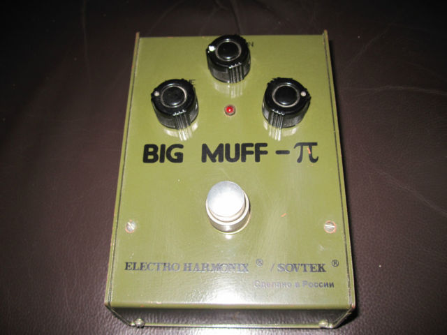
I had one of these, just like in the photo above. I hated it! IMO it sounded lame on guitar and bass! It was too clean sounding and didn't have that liquidly Muff tone. Totally over rated. I sold it on eBay, complete with the wooden box, for more than I paid for it new! My reference for Muff tone was my guild foxy lady. ;)
ReplyDeleteHave just built this effect. Made some changes to the board to stick strictly to version 7C and its stupid use of 1nf caps :P I hope Mark will forgive me for using standing resistors on his layout.
ReplyDeleteI keep on thinking that this is too bassy for guitar, and too mild for being a BMP, but anyway, you get some sounds out of this box, that you can't get with another BMP, so it's now a new adition to my BMP & Clones army.
Hope you like it:
https://scontent-b-mad.xx.fbcdn.net/hphotos-ash4/1463191_571067106298475_204304815_n.jpg
Made this with MPSA18s and replaced some diodes with leds. Really like it. I'm starting to think that there's something wrong with my triangle muff because this green muff sounds so much better.
ReplyDeleteWell... the fact is that if you use leds instead of diodes (1N914, the closer ones to the original russian), and MPSA18 instead of 2N5089 (once again, the closer match to the russians), being in any case the diodes and the trannies the most important part in the BMP tone.... I'm afraid you don't have a Green Russian :P
DeleteThere's a nearly verbatim clone of this effect, using germanium trannies and clipping leds, called Hoof, and sounds no way close to a BMP.
So, it may sound great, no doubt about it, but a Green russian with MPSA18 and leds as clippin diodes is not a Big Muff V7, but something "similar".
BR
indeed :)
DeleteThis comment has been removed by the author.
ReplyDeleteFinally took the time to build the green russian, with a few mods, and its epic. Even better then some real ones I've played. I tracked down the the actual russian transistors and diodes that could have been used, gain matched the transistors, ~780hfe, and it's totally glorious.
ReplyDeletehttp://s909.photobucket.com/user/rocket8811/media/IMG_2853_zps557e9cf4.jpg.html
I just finished this, and the volume and tone knob act totally normally, but the sustain knob seems like its acting as a gain AND volume at the same time. Volume cranked, and sustain down, I get no signal. Is this normal?
ReplyDeleteIt shouldn't be silent fully ccw, the 1K resistor that Sustain 1 attaches to should mean that there is still something coming through, albeit not very much. But yes I would expect the volume to drop a lot too, the Sustain pot essentially dumps the signal to ground with just the 1K resistor stopping it being completely dumped.
DeleteSo, it's not just a "distortion" knob? That's fairly normal?
DeleteYes it is just as distortion knob, it just works different than for instance the way the gain control works in a TS type pedal. The Big Muff has cascading gain stages and the Sustain control is before the stages in the circuit. Dumping some of the signal to ground reduces how much of the signal is slamming into the gain stages, and so reduces distortion by attenuating the signal before amplification.
DeleteTested it on a "real" amp, and not the tiny practice amp in my workshop. You're absolutely right, and it's not completely silent. I'm not used to distortion knobs cutting volume so drastically, so I assumed I screwed up. Thanks!
Deletehttp://instagram.com/p/jZ7GhADZKr/ Here's a pic!
DeleteJust finished my build last night, and it's almost working, except that the LED doesn't light up, and the pedal itself sounds extremely touchy and sensitive, like a broken DBA Robot. The signal pops from loud to quiet very often, and is just plain temperamental. Any idea what the issue might be?
ReplyDeleteHow do you think this would sound with a pair of MP35's in the Q positions?
ReplyDeleteIs it possible to split the Tone control into separate Bass and Treble controls?
ReplyDeleteI'd like to be able to adjust the bass and treble independently.
Maybe you can consider replacing the BMP tonestack with a Baxandall tonestack? http://amps.zugster.net/articles/tone-stacks#Baxandall
DeleteI think that'll be quite hard to implement on this layout. Possible, yes, but practical.. I don't think so.
Delete+m
I've just about finished building this, but I'm having an issue. I've got the board all soldered and all the off board wiring done and it's all connected with clip on leads to test. When I engage the circuit, it is really quiet and there is no fuzz, just a clean signal. On top of this, when the sustain is all the way up, it pretty much cuts off the signal entirely. Any suggestions where to start my trouble shooting? All solder joints look alright, all transistors test OK, and I couldn't find any solder bridges with the multimeter.
ReplyDeleteI put a picture of my board at http://i1226.photobucket.com/albums/ee414/OregonFencing/2014-04-15125333.jpg
Err... nevermind I found a cut that wasn't really cut. Duh. Now I just need to fix the issue with picking up radio signals with an external power supply. Even with that this thing sounds amazing!
DeleteTry a 100R resistor in series with the supply and input wires, and a low value cap like 100p from the input wire to ground. The cap will fit underneath Q1.
DeleteThanks, I'll try that! Just to make sure, you mean 100R between the 9V supply and the board and another between the input and the board?
DeleteYes. So 2 x 100R resistors inline with the input and 9V wires. Those along with the cap are all things recommended to reduce or remove RF interference
DeleteI added the cap and resistors and swapped my input lead for shielded wire. It cut down on the RF issue, but didn't eliminate it. I'm going to chock git up to poor wire routing on my first build. At this point the RF is quiet enough to be usable and it sounds pretty good otherwise. Thanks for the help and even more for this site!
DeleteHmm...my build worked great for a while but now the sustain knob doesn't seem to be doing anything, its just a preset amount of distortion at all times (volume and tone work fine.) I tried swapping the pot but its still happening...what else should I look at?
ReplyDeletePots usually go all scratchy before they go bad. More likely a loose wire, or cold solder joint. Start where the wires for that pot attach and follow the circuit with a magnifying glass. It will probably become obvious.
DeleteIf I wanted to add in a Subs switch similar to the one found on the Mastotron, which cap would I need to hook a switch?
ReplyDeleteI have problem with the v7, only little crapy sound out, it's verified isn't it?
ReplyDeleteYes. I'd be very surprised if there was a problem on any of the Muff layouts because they're all very minor variations on the same template, often just part values are altered.
DeletePost your transistor voltages and see if that gives a clue
here is my voltages:
ReplyDelete0.85 E 0.12 E
1.44 B 0.72 B
4.8 C 4.47 C
4.65 C 8.49 C
0.72 B 0.17 B
0.12 E 0 E
Q2 is looking suspicious to me. There shouldn't be anything like 8.49V on the collector when you look at the voltage you're getting at Q1 and Q3 with the same value bias resistors. So check all around Q2 for parts placement, soldering and check for unwanted bridges. As always, knife the gaps and make sure the cuts are clean
DeleteYess! Bad resistor value under Q2, thanks a lot Ivlark! Last question, there are mod to do to use it fwith bass or generally it works well like it is? I see that many bassist use it.
DeleteThanks again!
So I built this and for the most part it works. Sounds great, all pots work correctly. The switch is wired up, I triple checked the connections with a meter and they are good continuous joints. Yet the switch has such little effect on the sound of the pedal. You cannot really tell at all with the tone at low setting, and with the tone at high setting, it is the slightest change.
ReplyDeleteHere is my build http://i.imgur.com/8ABwYKz.jpg (Note the missing 100uF Cap bottom right was added after pic).
Is the low effect of the switch normal or is this a problem somewhere. If it is a problem, what should I be looking for, I am running out of ideas here!
Cheers
If you can't tell the difference then something is definitely wrong. It's a very obvious difference. Will your multimeter measure capacitance? If so then put one probe on the collector of Q3 and the other on the Tone 3 lug. With the switch in the middle position you should get a reading of approximately 4nF. Put the switch in both other positions and see if the capacitance reading changes in line with the cap values you have on the switch. If it doesn't change then something must be wrong with the switch or one of the connections because the caps on the switch aren't being added to the 4n cap on the board. If the value is changing in line with the caps on the switch then measure all the transistor pin voltages to see if that may point to an issue elsewhere which could be affecting it.
DeleteAre the volume and sustain controls supposed to be interactive on this? If I have the sustain down on this I get no signal even with the volume all the way up.
ReplyDeleteNote: I changed Q1 and Q2 to MSPA18.
Something must be wrong with your build then. The resistor at Sustain 1 should stop it going silent in the fully counter clockwise rotation of the Sustain pot so you should always be getting something out of it.
DeleteWeird. I'll go over it again. Thanks!
DeleteI'm not seeing what it might be. Mind taking a quick look at my board?
Deletehttps://www.dropbox.com/s/svtiyqreed27mzv/Photo%20Jul%2005%2C%205%2059%2022%20PM.jpg
Well, I just noticed that I completely forgot the 100uf cap.
DeleteI've built the 1994 version it sounds great! I'm loving the sound but I hate the noise when it's on and your not playing I wanna add the noise gate mod. I think I might leave this one as is and try to add the gate on the next one. I boxed it in a electric mistress case from the 70's. I found the enclosure online for 10 bucks! Looks cool but it's huge.
ReplyDeleteAny chance there is a way to include a dpdt two position switch to toggle on and off the first stage of diodes? I know a popular mod is to take out the first stage, so i think it would be cool to switch it on and off. If so where on the circuit would I connect the switch to?
ReplyDeleteThanks in advance
Well it is easy enough to do. Just disconnect one side of the diodes and take a wire from them to the switch. Then from the other side of the switch contact solder another wire going to where the diodes originally connected.
DeleteI feel like I'm just missing something here. Where is the output? Is it just always in the same place so it isn't labeled? I have only built one other pedal from your layouts (The Vox percussion) and it was labeled on that schematic.
ReplyDeleteSomeone, please enlighten me!
Volume 2to output, its in he notes below the layout. Get used to checking the notes as they can include important connections and advice.
DeleteI can't believe I missed that down there. I even had 2 of my coworkers look at it and they didn't see it either LOL Thank you!
Deletei like to try some diode mods. which q (2 or 3) is considered 1st and 2nd gain stage?
ReplyDeleteThis comment has been removed by the author.
ReplyDeleteThe transistor voltages will give a clue if anything is wrong, but is the circuit boxed yet? The shielding provided by the box can solve a lot of noise issues.
DeleteI seem to be having a problem with my build. When I hit the switch, it takes a second before it comes alive. And when I play hard sometimes it seems like there is volume dropouts. Any idea?
ReplyDeleteIs there a way I could change the mid switch to a pot that goes from scooped to boosted?
ReplyDeletehttp://www.beavisaudio.com/techpages/BigMuffToneControl/
DeleteSimplified:
-Swap the 3n9/4n for 12n.
-Desolder the 22K resistor's (left from the cap you just swapped) upper lead and take that to "mids" 25K linear pot's lug number 3.
-Solder the lug 2 to ground.
-Done.
There would be other solutions too, the one above being the simplest.
You could also take two wires parallel to 3n9/4n. Wire the first one (doesn't matter which) to ~200k lin pot's lug 3. Connect the lug 2 of that pot to 10n cap and the other lead of that cap to the second wire.
Those are just the two ideas right off my head...
+m
Could I take the 22k upper lead to the row below, and make a cut after then connect mids 3 to that row?
ReplyDeleteThat should work.
Delete+m
Also what are the tonal differences between the two layouts. I tried finding two different green big muff but I could figure out which one it was.
ReplyDeleteAnyone have any ideas about my build problems
ReplyDeletePossibly a bad or broken cap. Extremely hard to tell which one. Start from the power filter (100µ).
Delete+m
Do you think just measuring them with a meter will work, or do I have to swap out them one at a time?
DeleteYou can't measure caps (or if they leak) when they are on circuit. Other components will mess with your measurements.
Delete+m
This comment has been removed by the author.
ReplyDeleteNo. That won't work. I'm thinking that's like a mash of both of the ideas i explained before. You're overcomplicating it... Why do you want it switchable?
Delete+m
Well I want a mid knob, but the footswitch is to bypass the tone circuit and that's why I added the extra track to remove the 10n from ground, but I also need to remove that 10k resistor (that was the 100k resistor from tone 3 to ground) from ground to bypass the tone circuit.
DeleteOk. That makes more sense. Still not sure if that'll work, but go for it...
Delete+m
I mean, implementing the working tone bypass as in V3 BMP isn't that simple...
Delete+m
Alright well we'll see how it works. Hopefully well...
DeleteJust an update, just finished last night and everything works great! The tone bypass and mid knob is really awesome. Thanks for the help!
DeleteJust finished the "1994" version and I have to day it sounds great, sort of a "smoother than most" Muff. Since I don't have the "stock" trannies, I used the first four 2n5088's I picked from the bag and they sound so good in there I am afraid to order the 2n5089 or BC550C's and swap them. The flat-mids mode is tuned just right - more mids, still Muff- sounding - but I'm not sure if I like the "boosted mids" function all that much - it seems to decharacterize what a Big Muff should be. Definitely recommended build.
ReplyDeleteHi, what's a depth control & how could i add it?
ReplyDeletethe depth control is a pot that is placed between two different input caps, one large one small. the idea behind it is that you can control how much low end you allow to enter the 1st stage of the muff, and thereby preventing it from getting muddy. this was done of the earthbound supercollider, and the blackout effectors musket. if you want to add it to this effect take a look at the schematic for the supercollider to get an idea what to do. its not that hard.
Deletehttp://www.bigmuffpage.com/images/schematics/Supercollider%20Big%20Muff%20Schematic.jpg
Thanks John.
DeleteNo prob man. Personally, I feel that with the mid switch a depth pot isn't really needed, but then again I built the later version and I used high gain transitors, >700hfe. The higher the gain of the transistor the more treble comes through, and you don't lose any low end either, and I use mine mostly for bass.
DeleteThe nice thing about the muff is that it's super tweakable, look at all the "new" boutique fuzzes that are simply modified BMPs, so you can get it to sound how you like.
I finished this and unity volume is with pot at about 20% Is this ok? Also is there any good way to fine tune output volume on board so unity volume is with pot at 12 o clock??
ReplyDeleteYou could put a resistor before the output to pull it back but ehhh, I'd just get used to the SHEER POWER of the muff. :)
Deleteto be honest the big muff has a massive, and i mean massive amount of output, so what you're getting is normal. i think mine has unity output at around 9 o'clock. one of the ways to tell if your build isn't right is that you get little output.
Deletebut, as charles said you can take and run a resistor between volume 1 and the board, which is ground. i'm not telling you what to do, but i think it's a waste of time unless you just want to have your volume knob at noon for looks.
I found that using a 250k for the volume pot brought down the overall volume a little bit. The voltage divider is just providing more resistance at a particular setting and makes the level control work a little better. Anyone else try this, or have any objections to that? I like the volume control a lot better, just not sure if I should be changing that part of the circuit. They seem excessively loud...
ReplyDeleteit's not really that we have any objections to what you want to do, it just doesn't make a lot of sense, as it's just the nature of the beast, and how the circuit is. it's like taking a booster and saying it has too much boost, or taking an overdrive and trying to remove the clipping so it's clean. if you're happy with having less output that's great. it's odd that increasing the pot lowers the output.
Deletetheoretically if you increase the value of a volume pot you're going to increase the overall output because as a voltage divider when you turn the pot increasing resistance you're going to prevent signal from dumping to ground. ie more resistor for the signal to go to ground. if you lower the pot you should increase how much signal is dumped to ground, as you turn the pot thereby decreasing output.
This comment has been removed by the author.
ReplyDelete