The Tone Reaper is a vintage style fuzz device based on the “3 knob” bender. It’s a silicon/germanium hybrid capable of producing an array of tones from every bender era with careful tweaking of the tone and fuzz controls. From thin and spitty to a growling crunch, all with a midrange punch to make it scratch and kick through any mix. The Tone Reaper will also please anyone looking for the higher gain Randy Rhodes style grind at it’s higher fuzz settings. All analog, true bypass and made one at a time by real humans in stuffy Akron,
Basically it's a modified Tonebender MKIII, with the biggest change being the Germanium darlington pair normally in Q1 & Q2 being replaced with a high gain Sillicon transistor.
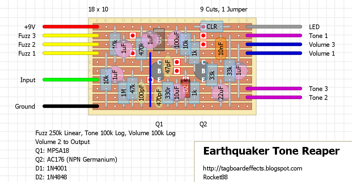
Thanks goes to Galapagos, who traced his Tone Reaper, schematic and trace here. You'll notice there's a diode he marked mystery, which from what I can tell looks like a 1N4848/1N914, so that may take some experimenting. Also, without knowing the hfe and leakage of the AC176, I can't say for sure what would be a good substitute, but you may want to try the typical NPN Germaniums typically use like MP38A, but these typically have little to know leakage while the original tonebender Q3 likes a lot of leakage.
Side comment. For those that want to have some more fun, you can build the Tone Reaper and put it in front of a Hoof, each on their own switch and make 2/3 of the Hoof Reaper, as we don't have a schematic for the switchable octave in between.
EDIT: for all those that want to make a Hoof Reaper we have a layout for the octave section, as it's the Tentacle. Build on Brothers of Fuzz.
An interesting project, definitely.
ReplyDeleteThank you Zach
What does CLR stand for?
ReplyDeleteWhat does CLR stand for?
ReplyDeletethat is the current limiting resistor for the LED, should be around 2,2k or 4,7k
Deleteit's whatever you like to use for your indicator LED, which is normally off board, but since there was space i put it on the board. makes things nicer and neater IMHO.
DeleteI think I read somewhere that the octave side of the hoof reaper is basically a modded copy of the Green Ringer (http://tagboardeffects.blogspot.hu/2010/12/dan-armstrong-green-ringer.html), so if you build that, you'll have the complete hoof reaper I think.
ReplyDeleteI also read somewhere that the Tentacle is a modded copy of the green ringer too.
Yep earthquaker was saying the octave was a green ringer. I read this so long ago that I have no idea how to document this claim, but you could throw a switchable green ringer in there to emulate the good reaper. Great idea and nice work Zach
Delete*Hoof Reaper not good reaper. Autocorrect!!!
DeleteAm building this right now. The reverse polarity protection diode seems to be backwards in the layout, though.
ReplyDeleteaccording to the schematic the positive is on the power rail and negative to ground. the line on the diode indicates the negative end, so it would be correct. on the schematic the diode is drawn incorrect compared to the polarity.
DeleteSorry! Then in that case, it appears they really are backwards and my "schematic" is wrong. My drawing of the diodes is correct (the orientation of the striped end) and I incorrectly figured that was the positive side, and marked the polarity accordingly. Just plain old lack of knowledge on my part. (To be fair -- for some reason the PCB holes are square for the positive sides of the electrolytics. But they're also square for the negative side of the diodes... Maybe just to confuse people like me.)
DeleteThanks for being patient while I learn this stuff...
No worries. I'll fix it when I get home.
DeleteThanks for posting. So wanting to build this!
ReplyDeletelayout has been updated to reflect the diode orientation as it is on the PCB board
ReplyDeleteIf this is truly based on the Tonebender MkIII then the mystery diode D2 is probably Germanium.
ReplyDeleteremember, just cause an effect is based on another effect doesn't mean that it's going to be identical. case in point, look how many pedals are essentially an elektra distortion, which is germanium, but most of the copies of it are silicon. or the hoof fuzz is a big muff that has 2 gain stages that are germanium rather then high gain silicons, and LED diodes instead of silicon.
Deletein any event, the diode in question in the tone reaper does appear to be silicon rather then germanium, in particular as i noted above appears to be a 1n914/1n4848, but it could also be a schottky diode, specifically ones that are sold as 1n34a.
as travis noted, you may want to breadboard it to test and tune, or if you're going to build the board socket D2 and try silicon and germanium diodes. personally, if i decide to build this i'm going to socket it to try different diodes and see what happens.
It is definitely based on the MKIII Tone Bender but that doesn't mean it uses the same parts.
ReplyDeleteIf you look at the guts it appears to be a silicon diode. That diode is going to have a pretty significant effect on the overall sound IMO it should be breadboarded or socketed
Verified! Didn't have any AC176s so used AC127 with Hfe of 112 and 0.79mA leakage. Socketed D2 ,100p an 470p. Tried 1N4148, 100p and 470p first and it sounds real good. Tried with 10nf and 4.7nf with the 1N4148 and its a bit too bassy for my liking. Tested a few other values and different Ge and silicon diodes but preferred the 1N4148 withe the 100p and 470p. Thanks Zach & Galapagos.
ReplyDeleteSweet. I'll mark it when I get home from the lab. Great job on the verification.
DeleteCan I use npn silicon instead of Ge for Q2?
ReplyDeleteQ2 (Q3 in a normal MKIII) generally wants some leakage to bias properly. It's worth a shot anyway.
ReplyDeleteThanks for answering Travis, I'm thinking about use the components that I already have, but as you said, that's significant point.. thanks
DeleteYou could try to simulate leakage with a resistor between the base and collector. This isn't necessarily a perfect solution but sometimes works alright. Be mindful of the fact that Si transistors usually have much much higher hfe than Ge
ReplyDeleteThis comment has been removed by the author.
ReplyDeleteBuild it with a B100k pot for fuzz, 1N914 diode, BC550C & mp38a transistors. Is working!
ReplyDeleteWhat does the tone controll do? It's a really subtle change in tone.
ReplyDeleteThe tone control shouldn't be all that subtle. Check your tracks and make sure you don't have any bridges, and make sure the everything is in the right spot.
DeleteI'm also not getting any change with the tone control.
DeleteThis probably won't make a difference, but its labeled as Linear on the real pedal's pcb.
That will make a difference because of how the change happens. Change the pot to linear and see if it's different. That could be the issue.
DeleteFixed the pot, but the extreme ends woudl still have changed sound. According to the original layout on the forum. the 100nf cap shown here should be 10nf (103j). I thought that would fix things but I STILL have no change in tone.
DeleteDon't think this will help, as the extremes are almost the same
DeleteSomething is off is even changing the 100nF to 10nF, as that would affect the frequencies being affected. I think something is off with the build.
DeleteEven though the extremes will be the same the sweep will be affected, and in turn will affect how you perceive the tone change. So sometimes changing the pot taper will affect what you hear through the sweep.
My breadboarded test circuit also had very little change with the tone control, but that's using the printed cap values, and 2 unmarked random Si NPN high gain transistors just to see if the thing worked overall. I just re-checked the PCB against the schematic, and it appears to be correct...
DeleteI mentioned to AlexS that the real pedal has a bit of interactivity between the tone control and the overall volume & fuzz intensity. (Turning up tone raises volume and fuzz a bit, and vice versa). Is there any reason to think that transistor choice would affect the tone control's function? My guess would be that the cap values are to blame, but I'm a newbie.
I will post more gut shots in the forum a bit later, in case that helps shed any light.
It looks like a typical Big Muff style tone stack so I put the values into Duncan Tone stack and it matches my experience.
DeleteThe values on the layout above with the 100nf are basically flat: http://imgur.com/1J3D2Zk
When I changed the 100n to 10nf, as on the original trace, there's a slight bass roll off as I turn the pot CLOCKwise: http://imgur.com/uICNag8
The two resistors seem to be 33k (orange orange black red) so the capacitor values may be off.
Cool! While I don't have time to tinker much right now, I did just throw in a 1nF orange drop into that slot to see what would happen, and the tone sweep is far more pronounced now (though not necessarily lovely-sounding at the extreme end, considering my lack of proper transistors, etc. at this time). But it seems obvious enough that values closer to the 1-10nf range work much better than 100nf.
DeleteIt is BMP. Typical values would be 10n and 3.9n. Maybe that cap labelled 471J should be 4.7nF? It's the 470pF on Tone 3 to GND. Try changing that.
DeleteThe pot must operate backwards too, unless the pot lugs were labelled wrong?
DeleteYup -- the real pedal cuts treble as you turn clockwise.
DeleteI jumped to conclusions too quickly in my post above... I've been switching out values for both the 471J slot (as you suggested) and the 103J slot, and getting plenty of different results. I found 4.7nF to be too muffled for my taste, but its character changes when the 103J slot is changed too. So, I have no conclusions at this point...
This comment has been removed by the author.
DeleteThis isn't necessarily a perfect solution but sometimes works alright
ReplyDeleteMcx Tips Free Trial
Are we sure about the tone stack?
ReplyDeleteThe tone stack in the MKIII is not like the one in the BMP. The MKIII tone stack basically pans between a tiny output cap and a big output cap.
If this were the case, the 4n7 is certainly the correct choice vs the 470pf
I'm wondering now if the tone stack was traced correctly, or if EQD simply used a BMP tone stack instead..
Take a look at a MKIII schematic and let me know what you think guys. As I see it this is an error or a less effective BMP tone stack
Hey could I use ac128 instead of ac176?
ReplyDeleteNo the AC128 is PNP. The transistor needs to be NPN.
DeleteUsing a MP38A on mine.
DeleteUsed a 10nF capacitor instead of a 100nF. It's got a bigger sweep now. CCW the bass is rolled off, CW has a nice amount of bass. Guess I'll leave mine fully CW all the time so I could have done it with one less pot.
ReplyDeleteCannot find a 100 log pot. 1k seems to be the smallest, which still is 1000ohms, right? Tried musikding and uk-electronic. Does it work with a 1k too?
ReplyDeleteThat's too low a value. I'm not sure why you can't find 100k linear lots, but you can get them here for cheap.
Deletehttp://www.taydaelectronics.com/100k-ohm-linear-taper-potentiometer-with-solder-lugs.html
Got it, ordered a 100k lin, no problem to get one of these.
DeleteGreat. It's also a good pot to stock up on, since it's used to often.
DeleteThere's a "K" missing in the layout notes....
Delete+m
Oh shit. Can't believed I missed that. I'll fix it when I get home. Thanks miro.
Delete100n should be 10n too.
Deletemade the corrections.
DeleteIt's B100k on the original, as shown on the pictures in the forum thread.
ReplyDeleteAny ideas on what hFe I should shoot for for the ge transistor in this?
ReplyDeleteBuilt the board, tested it without the footswitch. The LED lights up, but there is only humming on the output. When I turn down the Volume put the humming goes silent when full CCW.
ReplyDeleteI am still unsure about the orientation of D1. Is the ring heading up or down?
correct the line on D1 is on the power rail (top row). you definately have a build error going on. i would post pics, a description of the problem, and transistor voltages in the debugging section of the forum.
DeleteLet it sit for a couple of days and had a fresh look at it today. Had the 1uf at the top soldered to the power rail and not the rail below. Changed that and *boom* works like a charm. Gotta box it and shorten some of the cables to make it a little quieter. But again, thanks for posting all those fantastic layouts and for the help with the debugging.
DeleteI am going to reflow some solder joints tonight. If this does not solve the problem I'll post some pics on the forum. Thanks.
ReplyDeleteI just built this board and it sounds great, except when I turn the fuzz all the way up it feeds back. Anyone know how to fix this?
ReplyDeleteHi, I have exactly the same problem ! when the fuzz pot is all the way up, an horrible noise is coming. What can we do to remove the noise ? Thanks
ReplyDeleteI built it as above except using an MP38 for the germ. The MP38 had an HFE of 80 with very little leakage. I tried a higher HFE - over 90 - but prefer the sound of the the 80. It is a very cool pedal, and mine is lower gain than most Tonebenders I have built, and I like that.
ReplyDeleteI also tried a 2N1308 with an HFE over 100 but the MP38 actually sounds a lot warmer and is quieter too. In mine the tone control adds bass a it is turned CW and doesn't really affect the treble at all. That's ok because the treble is just about perfect anyway.
With the MP38 I am getting a really good "vocal-like" tone which is less buzzy and harsh than the average TB. I really like this pedal.
I'm probably gonna put a small resistor before the pot to keep some resistance on there even when the fuzz is on full.
ReplyDeleteI built this, sounds good but output is dropped quite a bit from normal, say 25%. Is there something I can do to add output to match when it's off?
ReplyDeleteif you're getting that big of a drop it may be because your volume pot or a resistor value somewhere is too large.
DeleteThanks. I have no idea where to start. Any suggestions?
DeleteThis comment has been removed by the author.
ReplyDeleteFinished! After some swapping, I ended up with a higher gain AC127 and a germanium diode. Nice early Zeppelin/Sabbath type tones and straight up stoner with higher gain and tone settings. Seems to work well in front of a dirty amp too.
ReplyDeleteThis comment has been removed by the author.
ReplyDeleteMine was sputtering with terrible sustain, with the MPSA18, so I dropped in a 550c and the thing came to life! Hope this helps someone!
ReplyDeletesi yo tambien sufro de un gate horrible . preobare con un 550c para ver que tal me va gracias por el consejo
DeleteHope this helps someone. In the Reaper's manual, it says there's a bias trimmer inside to bias the germanium transistor to 4.5v, per usual. So might be worth socketing that 33k going to Q2's Collector!
ReplyDeleteI might give this a try as I've built a couple of these and have just been sticking an extra resistor at the end of the fuzz pot to get rid of the noise. Although wouldn't the bias resistor be the 10k not the 33k?
ReplyDeleteThis comment has been removed by the author.
DeleteOh, yeah, 10k for the silicon and 33k for the Germanium.
ReplyDeleteThis comment has been removed by the author.
ReplyDeleteThis comment has been removed by the author.
ReplyDelete