Here's a collection of vero (stripboard) and tagboard guitar and bass effect layouts that we have put together covering many classic and popular effects in growing numbers. Many of these have been posted on freestompboxes.org, so check that site out for great discussions on building your own effect pedals. Enjoy the builds and please also visit us on Facebook and Twitter
Original info:
"The Mag-Echo pedal simulates tube tape echo sounds by using the delay
circuit and a little bit of modulation. Tape echos have long been
regarded as a warm and very guitar friendly form of delay. The Mag-Echo
achieves similar results by using a touch of Lo-Fi delay, a slightly
filtered echo response to keep things warm, and some modulation.
Modulation, or “Wow and Flutter” in the tape world is a slight pitch
shift or wavering that occurs as the tape is pulled across the heads.
The modulation we use is similar to what we use in our Seafoam Chorus, a
slight wavering of pitch on the trails of the repeats. With a simple
set of controls for the delay – Time, Regen, and Level and with the “Wow
and Flutter” controls – Depth and Rate you can create some very vintage
or rather unique tones"
PedalPCB's schematic, info and pcb available here.
A
germanium/JFET booster. A unique sounding pedal which adds a beautiful
sheen to your bass’ top end and a bit of grit to the overall tone. It’s a
fantastic pedal for situations where you want a lift in your overall
level, during a chorus or bridge for example, with a bit of bawdy bump
via the germanium transistor. One nice feature is also the more
modern JFET transistor at the input which keeps the pedal
impedance-friendly when it comes to active bass pickups. This helps the
Phat Phuk to remain consistent whether you put a P-Bass in front of it,
or a Warwick Thumb. Another recommended use: As a simple preamp when
going direct into your DAW. Helps to de-sterilize your bass’s direct
tone and add a little life before the signal is converted to ones and
zeros. Something else that was considered when creating the Phat Phuk
B. Many clean-boosts offer way too much boost in my opinion. In any
normal playing situation, including intentionally slamming the front end
of a tube amp to induce the amp’s natural overdrive, one really only
needs a hefty thump to get the job done. There’s nothing wrong with
having a large amount of volume on tap, but a problem that can sometimes
occur is a lack of ability to fine tune the amount of boost you want.
When the sweep of the knob goes from zero to melt-down with one turn of
the knob, it gets tough to really dial in a precise amount of boost.
Also a slight bump of the boost knob (with a foot or nervous “live show”
jitters) can send things out of control. I know because its happened to
me. Went for the big chorus during a song, hit the clean boost (not
mine, this was long before Wren and Cuff existed) and tore the heads off
the people in the front, pissed off the sound man, and pretty much
ruined that song. Therefore, the volume sweep was reduced with the
Phatty. You still get a big gob of gain, and probably won’t ever need to
run the pedal “at 11″, but the trade -off is worth the extra control.
Just an example of what Wren and Cuff prides itself on: pedals that
sound superior, look beautiful, can take a beating, and are made with
the “real world” player in mind. In other words: A meticulous attention to detail.
A few notes:
1 - I posted the trace, board pictures, and schematic in the request section, here so everyone can take a look and check the trace.
2 - the Germanium Transistor in Q2 is a Chinese Transistor with the markings removed, but what can be made out is AX9. This is PNP, but the hfe is unknown, but the good news is the schematic has been verified by JohnK, big thanks, with a PNP Germanium with 91hfe. So for now, as I put in the layout notes use a PNP Germanium with at least 90hfe, but by all means test it with other values. Don't forget that if you're using Russians that many times transistors with lower hfe seem to act similar to others of higher hfe.
Layout 1:
Layout 2:
Tweaked the layout to make the bias trimmer an external pot. I chose a linear taper as it's common to use linear taper pots for bias adjusting and the trimmer should act linearly. JohnK used a 1k reverse log pot, but I think you won't get the full range you do with the trimmer by lowering the value.
And I may as well add this one as a separate layout so we know what versions the comments are based on. This changes a cap value and adds an Effect Level pot to the CE-2. If you want to add an Effect Level pot to the guitar CE-2, just use this layout and swap the 12n cap to the left of Q3 for a 33n. Or if you want the option of using both, use a DPDT on/on toggle like this:
1---4
2---5
3---6
Solder a 12n between 1 and 4, solder a 33n between 3 and 6, and connect wires 2 and 5 to the holes that the 12n should have connected to on the board.
This obviously isn't yet verified but it's so close to the guitar version that it will be good to go.
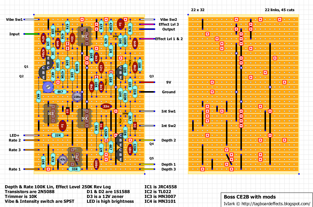
The BOSS Bass Chorus CE-2B is designed specially for a bass guitar, giving you the best result when used with a bass guitar.
The Rate, Depth and the Effect Level knobs serve to create various chorus effects.
Seeing as I'm on a roll with these at the moment I thought I'd add another popular chorus pedal. It's based on a few bits from 3 different schematics, and includes a Vibe and Intensity mods from the Tonepad scheme, rate LED and depth increase from Madbean's Pork Barrel and the schematic from Electrosmash which has a great in depth analysis of the CE-2 which is well worth a read, although I did decide to use common 2N5088 transistors as used in the Pork Barrel instead of the less common 2SC used in the original.
For the intensity switch I've opted for a 100p cap to go in parallel with the 47p between IC4 pins 5 & 7, but I'd recommend socketing the 100p and trying a few different values to see which works best for you giving the best range of tones.
One for a 125B I reckon.
Info about the fine original: The CE-2 effect unit is a new. compact version of the famous BOSS CE-l chorus ensemble, which has become one of the world's most popular units of its type on the market. Two separate controls are provided for independent variation of RATE and DEPTH to expand the creation possibilities. This advanced unit also has a fine S/N [S/N 90dB or more (IHF-A)] for lower noise operation. An LED lights to tell you at a glance when effect is on.
As an added bonus, here's an add-on stereo daughterboard option. Note that a stereo option isn't available for the CE-2 and so this has been inferred from the implementation in the CE-3. It should be good to go but should still be considered experimental until someone verifies, and so at this stage it's one for the tweakers.
All other connections to the CE-2 board have been removed to simplify the layout, and you'll see that the B connection will require the covering link to be pushed to one side slightly to allow the wire access to the hole. If you are including the Vibe switch option then a DPST will now be needed (or DPDT if they are easier to source), with the A wire also being switched.
And on Miro's recommendation this version removes the Madbean depth mod which took something away from the authentic CE2 sound to him. I've called it "Original", but have left the Vibe and Intensity switches in there as an option simply because you will still be able to set it in 100% original mode if you choose to using the switches (or omit them entirely of course if you prefer).
Addition - 5th January 2019
New version with Anti-Tick mod which will apparently cure all problems with noise. Thanks to Razvan S for the heads up.
Modded to include a depth pot instead of the switch used in the original, giving you variable depth control rather than just two preset levels. Not the best looking layout with too many links and cuts, but it's a means to an end, and it's hard to avoid when you have 4 ICs, 3 transistors and lots of interconnections, so I'm just happy that I managed to keep the size down. 21 x 28 will be a squeeze to get in a 1590B, but with only two pots and no other switches it shouldn't be a problem for most people.
I didn't have enough room to fit in pulldown resistors on the input and output and can't bring myself to add extra columns just to do that, so if you get any popping just add them to the stomp switch, 1M between input board wire lug and ground lug, and 100K between output board wire lug and ground lug. I may actually do it with surface mount resistors on the copper side of the board (the entire second row is ground).
Anyway, you all know what it is so no need to describe further. Manufacturers info about the great sounding, and very well priced original.
The classic chorus! Analog chorus pedal popularized by Kurt Cobain. The finest analog chorus sounds: from clear, rich and dimensional to warm pulsating warbles, can be intensified with the Depth Control. Simple tweaks generate exciting doubling effects. Chiming 12-string tone, or Leslie-like warbles.
Request for this nice sounding chorus/vibe pedal. Thanks to Scruffie for his schematic. It will fit in a 1590B if you want the aggravation, but a 125B would probably be a better choice.
The effect needs a 15V supply so you can either use a standalone 15V adapter if you have one, or build the included power daughterboard which with double the supply and then uses a regulator to reduce it to a stable 15V.
The schematic was based on a mono version of the old MN3007 Clone Theory, but this is the manufacturers information about the current XO version:
This recreation of the original 1970's Clone Theory is re-known for its very edgy chorus. Stereo outputs provide lush chorus and vibrato with a sparkling wash and liquid elegance.
CLONE THEORY, one of the most lush, deep and warm CHORUS/VIBRATO ever made, now in stereo. The CLONE THEORY’s depth and rate controls swing from one extreme to the other, giving the user an entire realm of possibility for tone.
[20th May: re-jigged slightly reduced the number of links, no corrections were made so the first layout posted should still be good]
and here's the stereo daughterboard for those wanting the option
Jack Orman's modifications to the Little Angel Chorus, which will hopefully help us get a bit more consistency with the builds. Information about the mods and a schematic can be found on Jack's blog here:
The Tri-Vibe was born from the idea of developing a true vibrato pedal that could be built without resorting to parts matching and complex adjustment procedures. Various frequency modulation alternatives were analyzed to accomplish this goal. There are numerous pseudo-vibrato implementations built around modified chorus and phaser pedals where the dry path is canceled, leaving only the wet signal. Several shortcomings to these approaches exist, such as: non-sinusoidal modulation (a sinusoidal LFO is a must for authentic vibrato), uneven frequency modulation across the audio band, poor noise performance, limited bandwidth, and intrinsic time delay. Delay chips such as MN3007 or PT2399 were dismissed mainly due their limited bandwidth and the intrinsic delay associated with them. The Wurlitzer vibrato was also considered, however its implementation required a rather large number of components. This left the all-pass stage alternatives. We initially thought that at least four all-pass stages might be necessary to achieve the goal of true vibrato, but after further investigation we found that as few as two all-pass stages could be optimized for linear phase variation within the guitar frequency range. This explains the unusual 15:1 capacitor ratio that sets the frequency of each stage, as this arrangement can produce a quite flat +/- 90 degree phase shift variation for frequencies between 80 Hz and 6 kHz. In order to implement the phase shift stages, the most common options were considered for the variable element: junction field-effect transistors (JFETs), light-dependent resistors (LDRs) and operational transconductance amplifiers (OTAs). JFETs and LDRs were discarded because they have wide production tolerances that would require precise matching and/or careful adjustments. On the other hand, OTAs are reasonably matched and predictable, so no parts selection or adjustments are necessary. Different OTAs exist, such as CA3080, CA3094 and LM13600/LM13700. We decided in favor of the LM13600 device since it includes the output buffers and contains a pair of linearizing diodes that allow an improvement in the dynamic range and S/N ratio. In addition, we added corresponding pre and de-emphasis networks at the input and output buffers to further improve the S/N ratio. The next challenge was to generate a suitable modulation signal. As a side note, in most phaser and chorus pedals adapted for vibrato mode, the lack of "proper" modulation vs. time produces an unappealing "motion sickness" characteristic. So, starting from a conventional triangle waveform generator with a predefined output level, a pseudo-sinusoidal signal is obtained by means of a 4k7 resistor, the 10k DEPTH pot, and two back-to-back diodes. The LFO is not finished yet, for the sinusoidal control signal needs to be exponentiated to obtain symmetric phase variation at each peak of the sinusoid. This final task is performed by the nonlinear arrangement of diodes and biasing resistor in the opamp stage U2b. Again, this section of the circuit requires no component matching or adjustments.
Original design by John Hollis, this version has been modified slightly to have a second vbias network specifically for the LFO IC with same value resistors as per Mark Hammer's suggestion in an attempt to solve the ticking problem some people have experienced.
Tweakers may want to add a Chorus/Vibe switch, and if so you can do this by switching out the 10K resistor directly to the left of IC3.
Video of Geiri's build of this layout:
Original version
Modded version with Chorus/Vibe switch
Modded version with Chorus/Vibe switch and 3 speed Mode switch
Another one of these nice little PT2399 projects to try out. This was a from a schematic posted by Merlin Blencowe and it seems to give a nice range of vibrato and chorus sounds for such a simple design, using just the PT2399 IC and nothing else driving it.
Clip made by Merlin (he posted that any noise was due to his recording setup and not the effect).
Yes the chips can be temperamental, but the results can be great for some of these effects. Just don't forget to buy 10 x PT2399's and keep trying them until you find one that works :o)
Another great sounding circuit here from Rick. His explanation:
I've had the idea to try a PT2399 chorus ever since I modded my Clari into a Clari Cubed. The challenge with the PT2399 is to get the delay time as short as possible while still having some wiggle room for the LFO injected into pin 6. I've tried PNP, NPN, FET and LDR - fail! The delay time is either too short for the LFO to have any wiggle, or too long and latency is obvious.
So, screw using pin 6, just ground the MF for the shortest possible delay time and instead modulate the vref at pin2. Shortest possible delay with as much LFO wiggle as you want. In fact it has to be tamed down or you're into tape wobble type effects.
Those familiar with the PT2399 family of delays will recognise homage to Rebote and the Clari in the input buffer and output section respectively.




.png)


