Here's a collection of vero (stripboard) and tagboard guitar and bass effect layouts that we have put together covering many classic and popular effects in growing numbers. Many of these have been posted on freestompboxes.org, so check that site out for great discussions on building your own effect pedals. Enjoy the builds and please also visit us on Facebook and Twitter
"This all-analog unit is a reproduction of the tone enhancing
circuitry contained within the most widely used wireless system
throughout the 1970's to mid 1980's, the Schaffer Vega Diversity System
(SVDS). Emphatic users of the SVDS included Angus Young, David
Gilmour, Eddie Van Halen, Carlos Santana, Peter Frampton, Peter Green,
Joe Walsh, Don Felder, Elliot Randall, Jerry Garcia, Bob Weir... and an
endless list of legends who are responsible for some of the best guitar
parts ever recorded."
Schematic available here.
anyway we could possibly get a nady td-1/ guyatone TO-2/ Westbury w-20 someday? I thought the real tube works would sound very similar but it dosent nor either does the fuchs tube pedal.
Hi Alex, I think you can tag this verified. I used a diy LDR/LED for the Vactrol and BAT46 was the closest I had on hand. I get some breakup with the limiter pot past 1 o'clock, assuming it must be due to the LDR/LED combo. Or maybe it is supposed to do that? Thank you for the layout! Aloha! Mitch
THANKS BROTHER! THis very similar to the preamp compandor in the shaffer wireless that every single rock star used in the mid seventies through the 80's. Its the only thing Angus used for his tone , I am waiting for the nsl 32. I ordered fron china today its gonna take a while i didnt realize it was 30 to 60 day shipping ha ha . i will verify asap
Hi everyone, could you explain to me how to connect the NSL 32 to the led? The NSL has 4 'legs', of which two go to the circuit, but what should I do with the other two? Can't make it up from the layout. Would be a great help thnx.
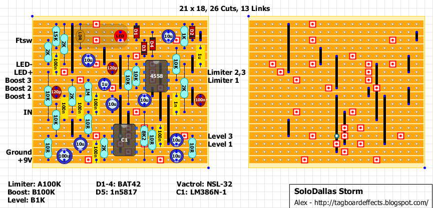
Hi, What is shown on the layout in the shaded area is basically what is inside of the NSL-32. The two "legs" that you mention that goes to the circuit is depicted as the LDR and the other two "legs" are the LED. There should be a colored mark or dot on the body of the NSL-32, that is the Cathode (-) leg of the internal LED. So these two legs go where the LED on the layout is depicted. Hope this helps.
Hey sylvain. The larger resistance ldr's are physically larger in size. You need a smaller one. I just had a mix pack lying around. The smaller sized ones worked. The big ones didn't. I use these clear green leds. No clue what type they are. Got them at a local shop that sells nte stuff. There like the led in a computer mouse but green. They work great for every optical effect I've ever made
@Gregory : BIG thank you !!! If I made this one, I will buy a NSL-32 like the schematic ;-) Not a LDR and a resitor sepatatly ;-) Thank you very much !
In the musikding german store, there is 2 different NSL-32 ref ... with different specs ... I suppose the good is the first (because 500 kOmhs is more likely than 25 MOhms for Roff I think ?!!!)
But can you confirm me please ?
1) https://www.musikding.de/Silonex-NSL-32_1 Silonex NSL-32, photocoupler with 4 leads. If of the LED is 40mA, der at If=20mA Ron=500 Ohm, Roff=500kOhm.
2) https://www.musikding.de/Silonex-NSL-32_2 Silonex NSL-32R3 photocoupler with 4 leads. If of the LED is 40mA, at If=20mA is Ron=60 - 150 Ohm, Roff=25MOhm.
I'd get them both, and with the one you don't use you can build a circuit to spy on your refrigerator and see if it's your roommate or your dog that's been drinking your last beer.
I’m not sure if others are having this problem but I used 1n60 diodes and an NSL-32 and getting no squish out of the limiter section. There is no voltage change on the LED, it’s just bright all the time. Are people sure their limiter section is working? I’ve been debugging this for over a month with no progress.
Hi ! it's not a distortion, but a kind of "booster" Mine doesn't create distortion, but give a colour to my tone ;-) If your amp is near crunch, the pedal give it a coloured boost to have a little bit more gain, but no disto, it gives this "particular back-in-black tone" ;-) (I've used a NSL-32 from musikding Germany, not separatly LED & LDR) I think you don't have a pb with yours ;-)
Built it. Love it. The limiter is very smooth and the boost into my simple valve amp achieves the "Instant Angus" tone....Pity that my playing doesn't.
I think the brown caps are ceramics,the yellow are box type film. perhaps he used a ceramic there because of the smaller lead spacing. I think a film would work also.
I’ve done also the storm, sounds nice but I have a very loud background noise like white noise. It’s in a box and with shielding wire for in/out jacks. Does this happen to anyone too?
Yes. See my response below. LM386N chips are inherently hissy. Supposedly, Angus' is also hissy and he uses a Hush noise reduction unit after the Storm.
So I just built one for me and one for a friend. I substituted 1N5818 diodes for BAT-42 and it worked fine.
I also reduced the indicator LED resistor to 2K2 as it was too dim and I sent the cathode directly to the switch.
The LM386N has enough internal hiss that if I attempt this again, I will mod the design for a single op-amp such as a TL072. I tried a negative feeedback (10K + 0.01uF) between pin #1 & #5 which muted some hiss, but also muted the highs. So I removed it.
I'm still unsure of where the footswitch connection on the vero actually goes. Can someone explain please? I assume the LED connections just go to the LED itself. Please help. :-)
I don't seem to get any effect change from the limiter pot. The only things I different are the 120p caps (I used 100p) and the BAT42 diodes (I used BAT46) would either of these affect it that much?
The limiter pot is quite subtle, but if you hit a chord with more gain/volume, you can clearly hear it ''limiting'' the insanity slight, at the very first stroke and subsequently choking the notes a bit. It's indeed not that noticeable but it's there and useful in some settings. If you cannot hear and feel this at all, recheck your wiring and what exact version of the optocoupler you used. I can confirm NSL-32, with no other denomination, specifically works here (there are also other NSL-32R2 and R3 variants and whatnot, maybe some don't work properly for this particular circuit). Also check that you really have it correctly oriented.

Nice layout. Is the FTSW label for the LED going to the Footswitch?
ReplyDeleteIt does
ReplyDeleteanyway we could possibly get a nady td-1/ guyatone TO-2/ Westbury w-20 someday? I thought the real tube works would sound very similar but it dosent nor either does the fuchs tube pedal.
DeleteHi Alex, I think you can tag this verified. I used a diy LDR/LED for the Vactrol and BAT46 was the closest I had on hand. I get some breakup with the limiter pot past 1 o'clock, assuming it must be due to the LDR/LED combo. Or maybe it is supposed to do that? Thank you for the layout!
DeleteAloha! Mitch
This comment has been removed by the author.
DeleteI resolved my breakup issue, error in my build. I settled on a Yellow LED/LDR combo. Thanks again for the layout.
DeleteI assume output is at level 2 on the pot (I didn't see it in the notes).
ReplyDeleteAnd where would sumthing like this be best placed is a signal chain? Where you would put an eq?
This comment has been removed by the author.
ReplyDeleteAlso I know a sonic Maximiser divides and deleys part of a signal so its not like this unit, but would you still say its in the same family?
ReplyDeleteTHANKS BROTHER!
ReplyDeleteTHis very similar to the preamp compandor in the shaffer wireless that every single rock star used in the mid seventies through the 80's. Its the only thing Angus used for his tone , I am waiting for the nsl 32. I ordered fron china today its gonna take a while i didnt realize it was 30 to 60 day shipping ha ha . i will verify asap
Hi everyone, could you explain to me how to connect the NSL 32 to the led? The NSL has 4 'legs', of which two go to the circuit, but what should I do with the other two? Can't make it up from the layout. Would be a great help thnx.
ReplyDeleteHi, What is shown on the layout in the shaded area is basically what is inside of the NSL-32. The two "legs" that you mention that goes to the circuit is depicted as the LDR and the other two "legs" are the LED. There should be a colored mark or dot on the body of the NSL-32, that is the Cathode (-) leg of the internal LED. So these two legs go where the LED on the layout is depicted. Hope this helps.
DeleteWow, mind is blown haha
ReplyDeleteDefinitely verified. Very picky with the ldr led combo. I used a clear green led. With a smaller resistance ldr. Sounds Great. It's a keeper
ReplyDeleteThanks Gregory
DeleteWhat do you mean by "resistance" for the LDR please ?
How can you choose the led color ?
greetings and happy new year !
Hey sylvain. The larger resistance ldr's are physically larger in size. You need a smaller one. I just had a mix pack lying around. The smaller sized ones worked. The big ones didn't. I use these clear green leds. No clue what type they are. Got them at a local shop that sells nte stuff. There like the led in a computer mouse but green. They work great for every optical effect I've ever made
ReplyDelete@Gregory : BIG thank you !!! If I made this one, I will buy a NSL-32 like the schematic ;-) Not a LDR and a resitor sepatatly ;-)
DeleteThank you very much !
Hi everybody !
ReplyDeleteIn the musikding german store, there is 2 different NSL-32 ref ... with different specs ...
I suppose the good is the first (because 500 kOmhs is more likely than 25 MOhms for Roff I think ?!!!)
But can you confirm me please ?
1) https://www.musikding.de/Silonex-NSL-32_1
Silonex NSL-32, photocoupler with 4 leads. If of the LED is 40mA, der at If=20mA Ron=500 Ohm, Roff=500kOhm.
2) https://www.musikding.de/Silonex-NSL-32_2
Silonex NSL-32R3 photocoupler with 4 leads. If of the LED is 40mA, at If=20mA is Ron=60 - 150 Ohm, Roff=25MOhm.
Thanks a lot ! Greetings !
Sylvain
I'd get them both, and with the one you don't use you can build a circuit to spy on your refrigerator and see if it's your roommate or your dog that's been drinking your last beer.
ReplyDeleteI’m not sure if others are having this problem but I used 1n60 diodes and an NSL-32 and getting no squish out of the limiter section. There is no voltage change on the LED, it’s just bright all the time. Are people sure their limiter section is working? I’ve been debugging this for over a month with no progress.
ReplyDeleteThis comment has been removed by the author.
ReplyDeleteThis comment has been removed by the author.
ReplyDeleteThis comment has been removed by the author.
DeleteHi ! it's not a distortion, but a kind of "booster"
ReplyDeleteMine doesn't create distortion, but give a colour to my tone ;-)
If your amp is near crunch, the pedal give it a coloured boost to have a little bit more gain, but no disto, it gives this "particular back-in-black tone" ;-)
(I've used a NSL-32 from musikding Germany, not separatly LED & LDR)
I think you don't have a pb with yours ;-)
This comment has been removed by the author.
ReplyDeleteBuilt it. Love it. The limiter is very smooth and the boost into my simple valve amp achieves the "Instant Angus" tone....Pity that my playing doesn't.
ReplyDeleteAre the 120pf caps ceramics? Thanks
ReplyDeleteYes Bob ;-)
DeleteGreat thank you! I still have to double check some stuff at the moment...
ReplyDeleteHi!
ReplyDeletei'm building that pedal :)
why is the JK-21 100n capacitor drawned differently than the others ? thanks !
Hi, i'm building this pedal, i have one question : why is the 100n cap at the far right drawned differently thatn the others ?Wich type is it ?
ReplyDeleteI think the brown caps are ceramics,the yellow are box type film. perhaps he used a ceramic there because of the smaller lead spacing. I think a film would work also.
DeleteI’ve done also the storm, sounds nice but I have a very loud background noise like white noise. It’s in a box and with shielding wire for in/out jacks. Does this happen to anyone too?
ReplyDeleteYes. See my response below. LM386N chips are inherently hissy. Supposedly, Angus' is also hissy and he uses a Hush noise reduction unit after the Storm.
DeleteSo I just built one for me and one for a friend. I substituted 1N5818 diodes for BAT-42 and it worked fine.
ReplyDeleteI also reduced the indicator LED resistor to 2K2 as it was too dim and I sent the cathode directly to the switch.
The LM386N has enough internal hiss that if I attempt this again, I will mod the design for a single op-amp such as a TL072. I tried a negative feeedback (10K + 0.01uF) between pin #1 & #5 which muted some hiss, but also muted the highs. So I removed it.
Very cool, a little noisy but as expected from an LM386(whatever variant, I tried many). Here is my build:
ReplyDeletehttps://hgecontraptions.blogspot.com/2023/05/solodallas-storm-booster-v1-clone-143rd.html
Thanks!
I think you may have answered my question on you blog. Thank you.
DeleteI'm still unsure of where the footswitch connection on the vero actually goes. Can someone explain please? I assume the LED connections just go to the LED itself. Please help. :-)
ReplyDeleteI don't seem to get any effect change from the limiter pot. The only things I different are the 120p caps (I used 100p) and the BAT42 diodes (I used BAT46) would either of these affect it that much?
ReplyDeleteThe limiter pot is quite subtle, but if you hit a chord with more gain/volume, you can clearly hear it ''limiting'' the insanity slight, at the very first stroke and subsequently choking the notes a bit. It's indeed not that noticeable but it's there and useful in some settings. If you cannot hear and feel this at all, recheck your wiring and what exact version of the optocoupler you used. I can confirm NSL-32, with no other denomination, specifically works here
Delete(there are also other NSL-32R2 and R3 variants and whatnot, maybe some don't work properly for this particular circuit). Also check that you really have it correctly oriented.
Sorry I never replied. I have parted ways with the acca dacca tribute show and haven't looked at the Storm again. Into the stack it went.
Delete