I recall reading how most of the Mudhoney DIY builds were just not sounding right.. Recently re-traced on FSB by Kasper, from his V1.1 version of the pedal - there may have been a fault with the schematics that previously floated around the web. When i saw this, i thought "the switch shouldn't work like that".. But it seems like it really does, and with this configuration, instead of the Ruetz-style mods on the Rat, one may finally get that Mudhoney (err.. tuned Rat?) tone out from a stripboard. There are the BJT transistor buffers in place to keep the topology close to an idol, but obviously the electronic switching is removed to accomodate true bypass. The oldee PSG demo may look outdated today, but it does not sound bad. And hey! It starts with a Dinosaur Jr riff with the pedal!
I'll leave a note on the orginal take of this layout...
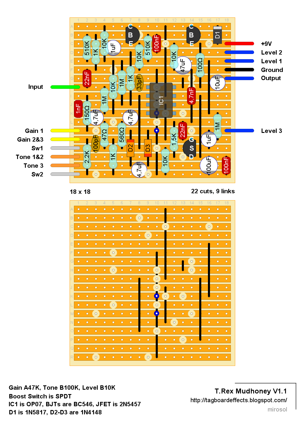
..And there's been slight development. This V2 of the layout incorporates 47R CLR for power supply and a 10K pulldown at the output as on Kasper's later revision of the schem. Making this now verbatim with the original. I doubt it'll sound any different from the slightly smaller layout above. But for the sake of completeness.. Here's a layout again as revision 2.

Verified. Thank You!
ReplyDeleteWow. That was quick!
DeleteHow does it sound? I'm asking 'cause it would be great to know if this sounds like the original..
+m
I tried to match to the demo video... functions the same. Sonically almost the same but i used BC550s, and 5458.
DeleteExciting!
DeleteAnd many thanks for verifying the layout - I am thrilled to hear that my tracing has paid off already :-)
/K
BJTs act a buffers (impedance transformers) and thus, don't affect the tone much. Anyway. Nice. I'll tag it.
Delete+m
this is exciting!
ReplyDeleteIs it a BC546B?
ReplyDeleteYes it is
DeleteThis comment has been removed by the author.
ReplyDeleteThanks for the layout. Did put this one together following the first smaller layout but having issues with it. Seems to work only when touching the side of the veroboard between level 3 and 100nf (bottom right) with my finger and completing the circuit. Any ideas where to troubleshoot? Have checked for solder joints and cold solders but at this point feeling a bit hopeless. Pots and switch seem to work as should when my finger puts life into the circuit.
ReplyDelete- Sampo
I remember that I liked the T.Rex Dr Swamp better, I think it was based on the Rat, too.
ReplyDeleteMud honey II is just doubled the circuit of Mudhoney V1.1?
ReplyDeleteOr it has different circuit?
Can i build 2 of v1.1 and put it in a box from this circuit?
I would think it is more or less just two mudhoneys, but there might be slight differences - can't tell as I haven't seen the schematic or the inside of one. But I would just try it out!
DeleteIs it possible to modify the old vero layout somehow to get the correct sound? I still have that built and would be interested in a modification.
ReplyDeleteI would probably just build the new board and repurpose the transistors, IC, switches and jacks from the old one. I think it will save you from some headaches
DeleteI've now built the V2 layout and can verify that it plays exactly like the one I traced
ReplyDelete- finally I can sell that one. :-)
/K
hello everyone, here is a gerber for those who want to use it, the tagboard has approximate measurements of 100mmx100mm
ReplyDeletehug and good week
https://www.pcbway.com/project/shareproject/TAGBOARD_FOR_PEDAL_PROJECT_tagboardeffects_100mmx100mm_e6d16693.html
Hello! I was wondering if anyone knows any schematics for creating an XoR switch in a pedal like is found on a trex mudhoney II. I'm going to be stuffing two of these single mudhoneys into a single enclosure and I want to the switching functionality of the mudhoney II, i.e. when I press one switch it selects the first side, if I press the second switch, it deselects the first side and selects the second, if I press the second switch again it will bypass the entire pedal. Anyone have any ideas?
ReplyDeleteSearch for “two fx toggle flex“ at musikding.rocks. I guess I posted the schematic and vero layout at freestompboxes as well.
DeleteYup, that's the final version. The LED resistors R11, R12 are critical, if they are too small, the relay won't work.
DeleteThanks again mate, will look at building one of those myself now!
DeleteDoes anyone else think it would be great (although tedious) if these pedals were tagged by transistors and ic? As a poor noob with very few components it would help me to find stuff i can actually make.
ReplyDeleteHey I just want to say I think there's an issue with this tagboard layout.
ReplyDeleteThere's a 1M pull down resistor added to this board at the signal input, tied to ground, that's not in the original schematic, in order to reduce popping when switching. However, the bias resistor of Q1 (R6 in the schematic) should be increased from 510k to 1M in order to maintain the already low-ish input impedance of ~500k, else it would be lowered to ~330k, due to the parallel pulldown resistor.
This resistor is located at the top right of the board in case anyone wants to change this themselves. Just change it to a 1M.
This comment has been removed by the author.
ReplyDeleteI just bought a Dr Swamp mk2. Hope I can trace it soon.
ReplyDeleteMark, you posted a schematic for the Comp Nova some years ago. Maybe some people might be thankful for a layout? The newer version uses a LM13700, which is still easily available.
Schematic is here:
http://valentinych.ru/o-zvuke/gitarnye-effekty-firmy-t-rex/
Nice sounding Rat variant. It is quite dark though. Using a C taper 100K seems to remedy that issue. It cleans up better than a stock Rat does, even on the dirty side. Sounds similar to a Rat or Rat 2 with a touch of the Ruetz mod to my ear. Nice Rat though. Thanks for the layout mirosol.
ReplyDelete