Here's a collection of vero (stripboard) and tagboard guitar and bass effect layouts that we have put together covering many classic and popular effects in growing numbers. Many of these have been posted on freestompboxes.org, so check that site out for great discussions on building your own effect pedals. Enjoy the builds and please also visit us on Facebook and Twitter
I know, I know. Another day another layout from me. I mean Jez, can't I let one of the other guys post a new layout for once this month? You guys must be sick of seeing my name pop up with a new layout... Anyways, this time I decided to do something different the the massive amounts of fuzzes I've been doing.
I've seen a few posts in the requests over the years for people looking for a preamp for Piezo pickups. The Barcus Berry 3000A is designed to work for acoustic piezo pickups but is also a buffer, preamp, and EQ. This is the only info that I could find on it:
The Barcus Berry 3000AE Piezo Buffer Preamp with EQ is specifically
designed to work with all Barcus-Berry electret microphone systems.
Features external bass, treble and volume frequency controls to allow a
wide range of adjustment. Includes a belt clip for unrestricted
movement.
Barcus Berry 3000AE Piezo Buffer Preamp Features:
• Designed to work with all Barcus-Berry electret condenser mic systems. • Features external bass, treble and volume frequency controls for a wide range of adjustment. Barcus Berry 3000A Product Specifications: Input (EQ) Flat Input Interface: RCA unbalanced Input Impedance: 2.2 Meg Ohms Maximum Input Level: 2.0 vrms Output (EQ Flat, Volume Max) Interface: 1/4" unbalanced Impedance: 2K Ohms THD: .008% @ 1kHz Noise: -92dBu S/N: 100dB Bass: +/- 12dB @ 50Hz Treble: +/- 12dB @ 10kHz Frequency Response: 5 Hz - 30kHz (+/- 1 dB) Power Supply
From what I see from the schematic I have no question that it will work with any Piezo pickup, as there doesn't seem to be anything really special to tell me it can only work with theirs. Mostly it's just marketing to get you to buy their pickup.
The Lehle Sunday Driver SW is a compact-format high-end preamp for all
types of electrical and acoustic instruments - a preamp that enables
electric guitars and basses, acoustic guitars, and also other stringed
instruments (such as violins, cellos and double basses) to realize all
of their musical potential. The switchable version expands the classical
Lehle Sunday Driver's features by an On/Off footswitch.
The Lehle Sunday Driver SW, with its high-quality JFET technology,
provides two operating modes. In D (= Driver) mode, the input signal is
amplified with zero modification, to eliminate the signal losses that
long cable routings and/or effects chains can cause. The signal remains
powerful and clear, and retains its dynamics. Mode S (= Sunday)
multiplies input impedance by four, bringing out previously inaudible
details and, as gain increases, imparting to the guitar a characteristic
and unmistakable warmth. There is no distortion at any stage, and the
signal always stays clean, even at a maximum gain setting of 15 dB.
Thanks to its studio-standard signal-to-noise ratio of better than -100
dB, the Lehle Sunday Driver SW is totally free of background noise. To
exploit the dynamics of tube amplifiers to the full, the input voltage
is also rectified from the power supply socket, then filtered,
stabilized and doubled to 18V.
In OFF status, the Lehle Sunday Driver SW provides two different modes
of operation - in TB (= True Bypass) mode, the input and output are
linked with zero losses to one another via a switch with gold-plated
contacts. True Bypass mode is the best option for a small set-up with
short cable routings and for when a treble-booster or a classical fuzz
pedal is looped in after the Lehle Sunday Driver SW. The line-driver
function, located at the start of the train or in an effect chain, is
the better solution for long cables and for complex effect board
configurations. Switch the Lehle Sunday Driver SW to TS (= True Sound)
mode, and it is active as a buffer, without amplifying or modifying the
signal in any way. In this mode, the Lehle Sunday Driver SW operates as a
totally neutral line-driver – equivalent to Mode D with the gain pot
turned all the way to the left. The Bypass mode option enables the Lehle
Sunday Driver SW to integrate ideally into any set-up, whether as a
battery-operated stand-alone unit, or in an existing pedal board.
Note: I removed the odd power network, which consisted of a diode rectifier and regulator, which should not be needed since it's supposed to run on +9VDC not +9VAC. According to the site, they claim there's a TB/Buffered switch which is not included on the schematic, nor did I see it on the PCB over at FSB when it was reversed engineered.
This ll discrete, MOSFET based circuit provides nearly 30db of
unadulterated clean gain boost with a minimum amount of tone coloration.
Note that you can also use this as an attenuator by turning the Boost
knob counterclockwise away from the noon position. It can also be used
as a powerful buffer with an input impedance of around 5M Ohms and an
output of around 1K Ohm, best used after your effects chain. This device
does not create distortion or overdrive on its own. However, it can be
used to drive your favorite amp or pedal into singing distorted sustain.
Simple, yet effective. Top notch components and circuit design assure
that your signal arrives to its destination in a truly pure state.
When you look at the circuit you can see it's basically a modified SHO.
Here is something a bit different and maybe useful!
It's an "effects loop buffer".
There isn't a schematic for it but you can find the original layout on Ceriatone's forum here.
You can also find all infos on their original manual here.
12/03/17 Layout updated! Moved 220K resistor and link from S to G on the top J201.
A
germanium/JFET booster. A unique sounding pedal which adds a beautiful
sheen to your bass’ top end and a bit of grit to the overall tone. It’s a
fantastic pedal for situations where you want a lift in your overall
level, during a chorus or bridge for example, with a bit of bawdy bump
via the germanium transistor. One nice feature is also the more
modern JFET transistor at the input which keeps the pedal
impedance-friendly when it comes to active bass pickups. This helps the
Phat Phuk to remain consistent whether you put a P-Bass in front of it,
or a Warwick Thumb. Another recommended use: As a simple preamp when
going direct into your DAW. Helps to de-sterilize your bass’s direct
tone and add a little life before the signal is converted to ones and
zeros. Something else that was considered when creating the Phat Phuk
B. Many clean-boosts offer way too much boost in my opinion. In any
normal playing situation, including intentionally slamming the front end
of a tube amp to induce the amp’s natural overdrive, one really only
needs a hefty thump to get the job done. There’s nothing wrong with
having a large amount of volume on tap, but a problem that can sometimes
occur is a lack of ability to fine tune the amount of boost you want.
When the sweep of the knob goes from zero to melt-down with one turn of
the knob, it gets tough to really dial in a precise amount of boost.
Also a slight bump of the boost knob (with a foot or nervous “live show”
jitters) can send things out of control. I know because its happened to
me. Went for the big chorus during a song, hit the clean boost (not
mine, this was long before Wren and Cuff existed) and tore the heads off
the people in the front, pissed off the sound man, and pretty much
ruined that song. Therefore, the volume sweep was reduced with the
Phatty. You still get a big gob of gain, and probably won’t ever need to
run the pedal “at 11″, but the trade -off is worth the extra control.
Just an example of what Wren and Cuff prides itself on: pedals that
sound superior, look beautiful, can take a beating, and are made with
the “real world” player in mind. In other words: A meticulous attention to detail.
A few notes:
1 - I posted the trace, board pictures, and schematic in the request section, here so everyone can take a look and check the trace.
2 - the Germanium Transistor in Q2 is a Chinese Transistor with the markings removed, but what can be made out is AX9. This is PNP, but the hfe is unknown, but the good news is the schematic has been verified by JohnK, big thanks, with a PNP Germanium with 91hfe. So for now, as I put in the layout notes use a PNP Germanium with at least 90hfe, but by all means test it with other values. Don't forget that if you're using Russians that many times transistors with lower hfe seem to act similar to others of higher hfe.
Layout 1:
Layout 2:
Tweaked the layout to make the bias trimmer an external pot. I chose a linear taper as it's common to use linear taper pots for bias adjusting and the trimmer should act linearly. JohnK used a 1k reverse log pot, but I think you won't get the full range you do with the trimmer by lowering the value.
Following a couple of threads in the forum where people had oscillation problems with certain effects that disappeared when a buffered pedal was placed before them, I said I'd do a post on here with a few different compact buffers that people could try tucked away in the box to place in series before the effect board.
So we have:
IC vero using TL071
IC perf using TL071
JFET basic buffer
JFET buffer with voltage divider for increased headroom.
Looking at the differences in sizes I'd be tempted to try the basic JFET buffer first, because if that does the job well enough it's so small that it should be easy to fit in any effect's box with the minimum fuss.
And seeing as I'm doing little ones tonight, this is the buffer section of the now discontinued (both product and company) Axess BS-2 Buffer/Splitter, and for once isn't just a rehash of a generic unity gain buffer (although to be fair none of these are going to be too far removed).
A charge pump gives the NE5532 a +/- 9V supply and so it is running with a 18V swing. I'm not sure what benefits you get from running a buffer at a higher voltage, but I'll leave that for those building it to judge.
The trimmer will let you tweak the gain to make sure you're at unity, or wherever you want to be. If you increase that trimmer to say a 5K then you can get a boost with your buff. Note that the charge pump IC is mounted upside down from the norm.
Info about the original: The BS2 has been designed as a solution to several problems that we’ve solved using custom-made buffers/splitters over the past several years. As a buffer, the BS2 should be used as early in the signal path as possible. Ideally it should be the first thing your guitar plugs into to, but unfortunately that can’t always be the case. Some Fuzz and WAH pedals do not like to be fed with a buffered signal. If you find these pedals don't sound right with the buffer in front of them, simply connect the buffer after these devices. In this situation, it would be ideal if these pedals had true bypass switching to ensure the BS2 gets the best possible signal it can... Using the BS2 in this application will prevent the loss of (1) signal level, (2) high end frequency response and (3) low end punch that is caused by cable capacitance and poorly designed input stage/circuitry of some effect pedals.
Traced from gutshots on the blog forum posted by hahafender, thanks for the pics buddy :o). Some of the traces on the unused side of the opamp weren't visible but the left hand side is a generic opamp buffer and that's the important bit. I think the resistors used on the other side we're just used as suggested by the IC manufacturers to do to unused channels. Not sure why he didn't just use a TL071 and so not require the 2 additional resistors, but I suppose that does make it at least appear further removed from the common opamp circuit that we've seen lots of times before.
Info about the original: This may be the greatest weapon you didn’t know you needed.
For those of us who are a little “pedal happy” there can be some downfall to our tone. When running a pedal board with more than one or two effects, something called “capacitance” happens. This natural problem happens due to the amount of cable or line that your signal has to travel through, not to mention bad switching systems in certain pedals. The result is a very audible amount of high-end loss, weak signal, flabby bass and uncharacteristic pickup behavior in guitars. Another problem is the assumption that all “true bypass” is good. This isn’t true and actually can be worse than imagined.
This is where the “Little Black Buffer” steps in providing the perfect input impedance to your rig and giving you the final result of clear, natural tone that sounds like you're plugged straight into your amp no matter how many pedals you use.
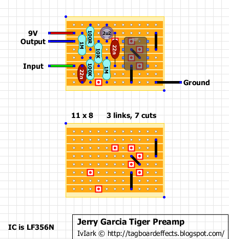
Request. Info about Jerry's original guitar with inbuilt electronics
Tiger was Jerry Garcia's main guitar from 1979 to 1989. It was built by Sonoma County luthier Doug Irwin. The Tiger is named after the tiger inlaid on the preamp cover located on the guitar's top, just behind the tailpiece.
The electronics of Garcia's Irwin guitars are unique, and feature an onboard preamp and effects loop. Much like a Stratocaster, the three pickups are selected with a five-way switch. Signal from the pickups passes through the tone controls, followed by an op-amp based buffer preamp, or Unity Gain Buffer, which is designed to prevent signal loss due to capacitance when long cables are used.
With an added Booster/Buffer switch. Info from the manufacturer about the original:
The MC401 is simple in design but superbly effective in solving a variety of mismatched line level and signal conditioning problems that can occur when combining effects. The MC401's circuit design has been used for years by CAE in the world's best guitarist's rigs to remedy these problems and rejuvenate the sparkle, punch and brilliance that can be lost. It can also be used as an ultra-clean boost (up to +20dB) for solos or to drive effects for more dynamics and sensitivity. Power: Single 9 volt battery, ECB003 AC Adapter or ECB004 AC Adapter for 18 volt operation (for increased headroom)
And for those of you who like the idea of the extra headroom, here's a version with a charge pump and a 9V/18V switch.
There are situations in which very long cable runs are necessary from the pedalboard to the amplifier, or a more powerful driving circuit is needed to the heavy load presented by devices in parallel. A good buffer box is the solution.
The best buffer board will present a high impedance to the input while having a low impedance output. This insures that the maximum clear signal will pass through unchanged to the output, and a low impedance drive can send the signal through long cables without losing much strength or response.
There are numerous special purpose chips that are designed as buffers for driving very long lines and/or capacitance loads. These ICs can be difficult to find and expensive. A simple solution for stompbox purposes is to parallel opamps and thereby boost the output drive. With attention to a few details, this is a simple project to build.
Request. The vero version of this that I already posted included axial caps, this keeps the size down by using all radial caps and will be more handy for someone wanting to add a small boost board to another effect for instance. Includes details for adding a master volume pot.
This will probably be a popular build for people who use a Fuzz Face (or similar) and also an older style wah, and have a problem putting them in the usual order. Info from Foxrox about their original: The Foxrox Wah Retrofit is a self-contained JFET buffer/amp circuit that gets installed into your Wah Wah pedal, giving it the ability to cut through any Fuzz Face or Fuzz Face clone. By essentially installing a "real" output section, the Wah Wah pedal becomes immune to the effects of loading, restoring range and depth to older, vintage Wah Wah pedals without affecting their vintage value. Newer, high-end "boutique" wah pedals, such as Teese RMC pedals also benefit from this mod because they are based on the same, classic inductor-based circuit. Since it is a basic JFET audio buffer/amplifier, this circuit can also be added to effects pedals that need more output, as well as effects that need more drive at the input.
The Fat Control is an on board guitar mid boost/buffer which includes a wide variable gain mid frequency power booster control and a built-in low impedance buffer that has been installed into a steel stomp box. The Fat Control boosts a wide mid frequency range for a more distinct natural musical frequency boost than all other mid controls. The frequencies selected give your guitar the best response and sustain possible.
Not a lot of info on this old pedal, but it was a request so I'll let Vince tell you about it! :o)
I've omitted the reverse polarity protection part of the circuit to keep it more 1590B friendly, but if you do want to add some protection just put a 1N5817 or 1N4001 in series with the 9V supply. The effect includes a buffered bypass and so only a SPDT latching stomp is required, or a DPDT if you want LED indication.
This is a bit of an unusual one because I'm not even sure what it is. It's based on a schematic done by Analogguru and is obviously a Cornish buffer in front of a booster, so what I am assuming is that the Guild Brian May is the treble booster, and the whole circuit amounts to the modifications done by Pete Cornish when putting the effect in one of his boards for Brian.
Some or all of that may be wrong as it is just my assumption, so please correct me if anyone knows more, but the thought of a Cornish buffer into a Brian May treble booster seemed too good an opportunity to miss so I thought I'd have to do the layout! :o)
The input socket should be taken directly to the board input and so only a SPDT stomp is needed for the switching because the buffer remains in circuit during bypass (the stomp is the "Sw#" connections shown in the layout). You will of course need a DPDT stomp if you want to include an LED. For those wanting true bypass instead of the Cornish buffer .... shame on you! :o)