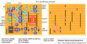
Came across this the other day and since I'm in the mist of finals I figured it would be a nice way to get my head away from my work and relax. Basically this is just a modified Ross Distortion, but has enough differences that I feel warrant a layout of its own, plus not sure how may people have seen it before.
List of differences from the source:
- Time for a Better IC: After "auditioning" the single
OPAMPs, I've decided to use a good 4558 in the Liquid Drive for
better all-around sonic performance, in this case a Burr Brown
OPA2134PA. You can also try all the other 4558-types, like the JRC
4558D and
4558DD, Burr Brown OPA2604, Texas Instruments RC4558P and several
others.
- Stabilizing the IC: Since this circuit utilizes a
dual IC, but actually uses only one of the two internal amplifiers, we
need to stabilize the
second unused amplifier. In order to do this we'll tie pin 5
(non-inverting input 2) to ground, and attach pin 6 (inverting input 2)
to
pin 7 (output 2).
- More Treble Response: For more treble response in the circuit, specially tailored for my modified Fender
Telecaster and Twin Amp, I changed the 10nF input capacitor to a smaller value, in this case a 3.3nF.
- Asymmetric Clipping Diodes: I personally prefer the
sound of asymmetric clipping. For the Liquid Drive I
chose to use 1N270 Germanium diodes for their warmer, more throaty
response compared to Silicon diodes or LEDs. They're also a
little more squishy and compressed sounding than Silicon diodes or
LEDs, which makes them sound more like tube distortion to my ears.
Using asymmetric clipping also enhances the harmonics and boosts the
output of the circuit. The only drawback is that the drive range
is decreased a little, but we'll make up for that in the next mod!
- More Gain: In order to recover the gain range lost by using asymmetric clipping, I've lowered the 4K7 resistor on
the 3rd lug of the "Drive" pot to 3K9...not a drastic change, but it does increase the available drive range.
- More Low-End Response: To get a little more low-end response out of the circuit, I increased the value of the 47nF capacitor that's attached to pin 2 of the IC to 68nF.
- Increased Output Level: In order to get a little more output from the circuit, I've used a 100K linear
taper pot for
the "Level" control. The linear taper pot will allow more output
sooner in the rotation of the pot, as opposed to a standard audio taper,
where all the useable output is in the 2 o'clock to 3 o'clock range.
The linear taper takes some getting used to, but I think it's better
to have that extra output sooner in the rotation range. The linear
taper pot is LOUD at 11 o'clock.
- Use Non-Polar Film Capacitors Instead of Tantalum:
In order to get more clarity from the circuit, I've replaced the two
1uF Tantalum capacitors with 1uF non-polar AVX boxed metal film.
They're larger than the tants, but I think their better sound
quality is worth making a little more room on the circuit board for
them.
- Power Supply Filtering and Polarity Protection Mods:
To add some extra nose rejection and polarity protection to the
circuit, I've added a 100-ohm resistor in series with the power supply
before the power makes it to the circuit, and then I added
a 100uF Electrolytic and 100nF Cermaic capacitor in parallel with the
power supply after the series resistor. These two added capacitors
provide superior noise/hum rejection for the circuit. I've also added a
1N4002 diode in parallel with the power supply after the series
resistor to help prevent damage to the circuit in case the battery or
power supply is connected in reverse polarity. To some these extra
parts may seem like overkill, but to me they're piece of mind :)
In the end you can try different diodes and Dual Opamps and see what you like best. I know I'm not the only one that's a big fan of the DOD250/MXR Dist+/Ross Distortion for it's great tone, simplicity, and the ease at which it can be tweak to your liking.


